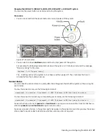
Preparing the 8335-GTC, 8335-GTG, 8335-GTH, 8335-GTW, or 8335-GTX system for
operation after you remove and replace internal parts
To prepare the IBM Power System AC922 (8335-GTC, 8335-GTG, and 8335-GTH) or IBM Power System
AC922 (8335-GTW and 8335-GTX) system for operation after you remove and replace internal parts,
complete the steps in this procedure.
Procedure
1. Ensure that you have the electrostatic discharge (ESD) wrist strap on and that the ESD clip is plugged
into a ground jack or connected to an unpainted metal surface. If not, do so now.
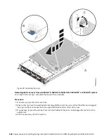
2. Replace the service access cover. For instructions, see “Installing the service access cover on an
8335-GTC, 8335-GTG, 8335-GTH, 8335-GTW, or 8335-GTX system” on page 99.
3. Place the system into the operating position. For instructions, see “Placing an 8335-GTC, 8335-GTG,
8335-GTH, 8335-GTW, or 8335-GTX system into the operating position” on page 103.
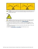
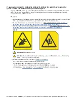
(L012)
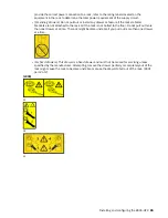
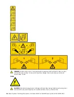
CAUTION: Pinch hazard. (L012)
Attention: For a water-cooled system, before you power on the system, ensure that cooling
water is circulating through the system.
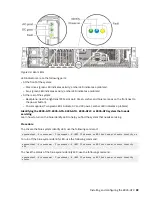
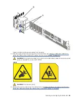
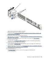
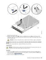
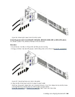
4. Replace the power supplies as shown in Figure 45 on page 95.
a) Place your other hand underneath the power supply.
b) Align the power supply (A) with the bay with the fan to the left.
c) Slide the power supply into the system until the latch (B) locks in place.
d) Repeat steps “4.a” on page 94 - “4.c” on page 94 for the other power supply.
94 Power Systems: Installing the System and Ordered Parts for the IBM Power System AC922 (8335-GTX)
Summary of Contents for Power System AC922
Page 4: ...iv...
Page 105: ...or or or or Installing and configuring the 8335 GTX 91...
Page 137: ......
Page 138: ...IBM...


