background image

Wireless LAN PCMCIA Card 


3

Federal Communication Commission 

Interference Statement 


This equipment has been tested and found to comply with the limits for a 
Class B digital device, pursuant to Part 15 of FCC Rules.  These limits are 
designed to provide reasonable protection against harmful interference in a 
residential installation. This equipment generates, uses, and can radiate radio 
frequency energy and, if not installed and used in accordance with the 
instructions, may cause harmful interference to radio communications.  
However, there is no guarantee that interference will not occur in a particular 
installation. If this equipment does cause harmful interference to radio or 
television reception, which can be determined by turning the equipment off 
and on, the user is encouraged to try to correct the interference by one or 
more of the following measures:   
 

1.  Reorient or relocate the receiving antenna. 

2.  Increase the separation between the equipment and receiver. 

3.  Connect the equipment into an outlet on a circuit different from that to which the 

receiver is connected. 

4.  Consult the dealer or an experienced radio technician for help. 


FCC Caution


This equipment must be installed and operated in accordance with provided 
instructions and a minimum 20 cm spacing must be provided between 
computer mounted antenna and person’s body (excluding extremities of 
hands, wrist and feet) during wireless modes of operation. 
 
This device complies with Part 15 of the FCC Rules. Operation is subject to 
the following two conditions: (1) this device may not cause harmful 
interference, and (2) this device must accept any interference received, 
including interference that may cause undesired operation. 
  
Any changes or modifications not expressly approved by the party responsible 
for compliance could void the authority to operate equipment. 
 

Federal  Communication Commission (FCC) Radiation Exposure Statement 

 
This equipment complies with FCC radiation exposure set forth for an 
uncontrolled environment. In order to avoid the possibility of exceeding the 
FCC radio frequency exposure limits, human proximity to the antenna shall 
not be less than 20cm (8 inches) during normal operation. 


Summary of Contents for PCMCIA Card

Page 1: ...W Wi ir re el le es ss s L LA AN N P PC CM MC CI IA A C Ca ar rd d User Manual Version 1 1 Aug 2002...

Page 2: ...laims any warranties merchantability or fitness for any particular purpose Any software described in this manual is sold or licensed as is Should the programs prove defective following their purchase...

Page 3: ...uipment into an outlet on a circuit different from that to which the receiver is connected 4 Consult the dealer or an experienced radio technician for help FCC Caution This equipment must be installed...

Page 4: ...ver special attention must be paid to the dangers of electric shock and static electricity when working with electrical equipment All guidelines of this and of the computer manufacture must therefore...

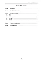
Page 5: ...1 Introduction 6 Chapter 2 Installation Procedure 7 Chapter 3 Configuring Utility 10 3 1 Status 10 3 2 Statistic 11 3 3 Site Survey 12 3 4 Encryption 12 3 5 Advanced 13 3 6 Version 13 Chapter 4 Techni...

Page 6: ...ne Wireless PCMCIA Card One CD Based Software Including Wireless PCMCIA Card driver utility and user manual One Quick Guide If any of the above items is missing contact your supplier as soon as possib...

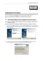
Page 7: ...turn to page 9 Note2 If you have installed the Wireless PCMCIA Card driver utility before please uninstall the old version first Note3 Be sure not to insert the Wireless PCMCIA Card before the instal...

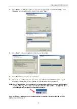
Page 8: ...start the computer now Then insert the Wireless PCMCIA Card in your computer Please wait for 2 3 minutes for the system to find the device Note When you complete the installation the Configuration Mon...

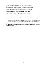
Page 9: ...em will find the device and search for its driver Please select the Driver Utility Drivers WinXP folder C Please wait for 2 3 minutes the system will restart the computer after it finishes the install...

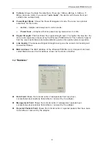
Page 10: ...lication 3 1 Status Click Change to set up the necessary parameters and click Submit after the configuration has been changed u Operation mode Shows the following network modes Infrastructure This ope...

Page 11: ...is indicator helps to find the most comfortable antenna workstation position for quality network operation u Link Quality The measured Signal Strength level gives the overall Link Quality and Connecti...

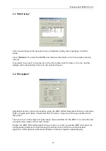
Page 12: ...4 Encryption Additional security can be achieved by using the WEP Wired Equivalent Privacy encryption WEP encrypts each frame transmitted from the radio using one of the keys entered from this panel...

Page 13: ...d Long Preamble The Short Preamble option improves throughput performance u Fragmentation Threshold The size at which packets will be fragmented Choose a setting within a range of 256 to 2346 bytes u...

Page 14: ...00M l LED Indicator Link l Power consumption 3 3V DC 500mA Tx 230mA RX l Operating Temperature 0 to 55 l Storage Temperature 20 to 70 l Operating Humidity 0 to 70 Non Condensing l Storage Humidity 0 t...

Page 15: ...astructure An integrated wireless and wireless and wired LAN is called an Infrastructure configuration Infrastructure is applicable to enterprise scale for wireless access to central database or wirel...

Page 16: ...o can recover the original data without the need for retransmission To an unintended receiver DSSS appears as low power wideband noise and is rejected ignored by most narrowband receivers What is Spre...

Reviews: