background image

3

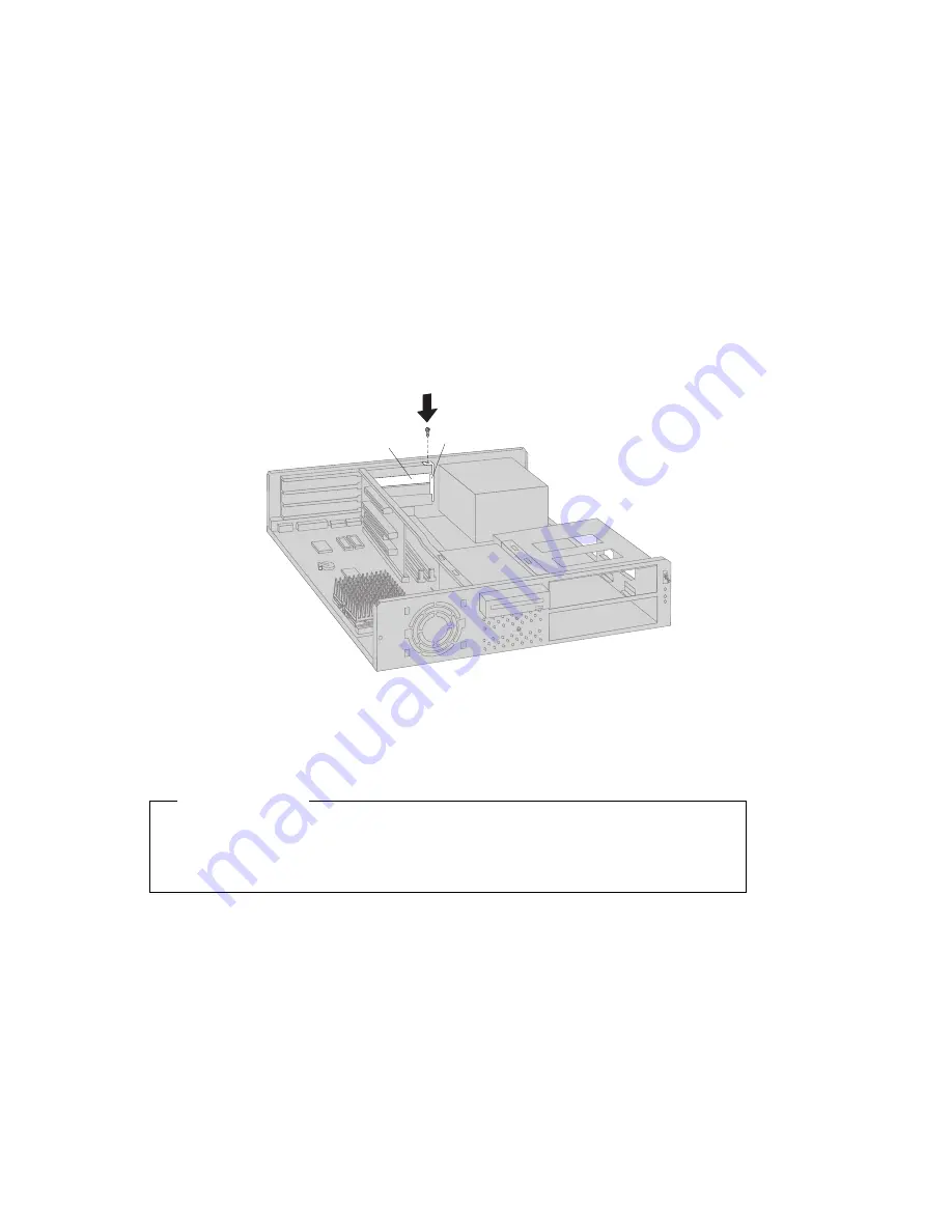
If you are not installing another adapter in this slot, install the expansion-slot
cover and attached bar. The following illustrations show the expansion-slot
cover being installed.

Attached Bar

Expansion-Slot Cover

Note:  

Removing an adapter frees up system resources. If you remove an ISA
legacy adapter, you must use the Configuration/Setup Utility program to set
the previously used resources to [Available]. For more information, see
Chapter 7, “Completing the Installation” on page 62.

What to do next

Ÿ

To work with another option, go to the appropriate section.

Ÿ

To complete the installation, go to Chapter 7, “Completing the Installation”
on page 62.


Chapter 4. Working with Adapters

35

Summary of Contents for PC 300 GL Type 6272

Page 1: ...Personal Computer Installing Options in Your Personal Computer PC 300 GL 6272 and 6282 ...

Page 2: ......

Page 3: ...Personal Computer Installing Options in Your Personal Computer PC 300 GL 6272 and 6282 IBM ...

Page 4: ... made to the information herein these changes will be incorporated in new editions of the publication IBM may make improvements and or changes in the product s and or the program s described in this publication at any time This publication was developed for products and services offered in the United States of America IBM may not offer the products services or features discussed in this document i...

Page 5: ... the Cover 5 Locating Components 6 Identifying Parts on the System Board 7 Chapter 3 Installing Options on the System Board 9 Installing System Memory 10 Installing Video Memory 14 Installing L2 Cache 17 Replacing the Microprocessor 19 Chapter 4 Working with Adapters 24 Adapters and the Riser Card 25 Adapter Configuration 26 Installing an Adapter 28 Removing an Adapter 32 Chapter 5 Working with In...

Page 6: ...g the Installation 62 Removing a Bay Panel 63 Replacing the Cover and Connecting the Cables 64 Updating the Computer Configuration 66 Appendix A Replacing the Battery 71 Appendix B Interrupt and DMA Resources 73 Appendix C Notices 75 Trademarks 75 Index 76 iv Installing Options in Your Personal Computer ...

Page 7: ...s to devices In the U K by law the power cord must be disconnected after the telephone line cable 2 In the U K by law the telephone cable must be connected after the power cord 1 2 1 Electrical current from power telephone and communication cables is hazardous To avoid shock hazard connect and disconnect cables as shown below when installing moving or opening the covers of this product or attached...

Page 8: ... the battery as required by local ordinances or regulations ATTENTION Danger d explosion en cas de remplacement incorrect de la batterie Remplacer uniquement par une batterie IBM de type 33F8354 ou d un type équivalent recommandé par le fabricant La batterie contient du lithium et peut exploser en cas de mauvaise utilisation de mauvaise manipulation ou de mise au rebut inappropriée Ne pas Lancer o...

Page 9: ...lectrotechnical Commission IEC 825 and CENELEC EN 60 825 for Class 1 laser products When a CD ROM drive is installed note the following CAUTION Use of controls or adjustments or performance of procedures other than those specified herein might result in hazardous radiation exposure Opening the CD ROM drive could result in exposure to hazardous laser radiation There are no serviceable parts inside ...

Page 10: ...es instructions for installing removing and replacing most options Also this book contains information to help you decide which options to add to your computer Note The illustrations in this publication might be slightly different from your hardware viii Copyright IBM Corp 1996 1997 ...

Page 11: ...ling and removing adapters and drives Chapter 5 Working with Internal Drives provides instructions for installing and removing internal drives Chapter 6 Working with Security Options describes features such as erasing lost or forgotten passwords Information on diskette write protection is also provided Chapter 7 Completing the Installation provides instructions for reassembling your computer after...

Page 12: ... Personal Computer About Your Software This publication provided only with computers that have preinstalled software contains information about the preinstalled software package Your Ready to Configure CD This publication contains information about the Ready to Configure CD that comes with your computer The publication also contains instructions for starting the CD The following publications conta...

Page 13: ...ffered with these models If your computer has three drive bays it is referred to as the 3 bay design If your computer has four drive bays it is referred as the 4 bay design These following naming conventions are used only where it is appropriate Instructions without these naming conventions apply to all computer models 3 Bay Design With the cover on bay 2 in the 3 bay design is not visible This ba...

Page 14: ...or a hard disk drive which does not have accessible media such as a CD ROM drive or diskette drive The 4 bay design has four expansion slots for adapters as shown in the rear view below Bay 1 Bay 2 Bay 3 Bay 4 Front View Expansion Slots Rear View xii Installing Options in Your Personal Computer ...

Page 15: ...troduction to the options and features that are discussed in this book Also important information about required tools electrical safety and static sensitive devices is discussed Important Before you install or remove any option read the safety procedures and component handling guidelines in this chapter These precautions and guidelines will help you work safely Refer to Using Your Personal Comput...

Page 16: ...ional floor stand or wall mount Also for security purposes you can add an optional U bolt The U bolt allows you to secure the computer with a cable and lock Installation instructions come with these options For the latest information about available options Within the United States call 1 800 IBM 2YOU 1 800 426 2968 your place of purchase or your IBM reseller Within Canada call 1 800 565 3344 or 1...

Page 17: ...ave a modem or fax machine attached to their computer must disconnect the telephone line from the computer before unplugging any power cords also known as power cables When the computer is reassembled users must reconnect the telephone line after plugging in the power cords 3 Unplug all power cords from electrical outlets 4 Disconnect all communication cables from external receptacles 5 Disconnect...

Page 18: ...Always handle components carefully Handle adapters and memory modules by the edges Never touch any exposed circuitry Prevent others from touching components When you are installing a new option touch the static protective package containing the option to a metal expansion slot cover or other unpainted metal surface on the computer for at least two seconds This reduces static electricity in the pac...

Page 19: ...dia see Using Your Personal Computer 1 For models equipped with a cover lock make sure it is unlocked 2 Disconnect all cables attached to the computer this includes power cords cables or lines connected to the input output I O ports 3 Remove the cover screw from the rear of the computer Slide the cover approximately 19 mm 0 75 in toward the front of the computer and lift it off The following illus...

Page 20: ... Removing the Cover on page 5 Expansion Slots Riser Card 3 5 inch Drive Bay 1 Bay 2 Bay 3 3 Bay Design Expansion Slots Riser Card Removable 3 5 inch Drive Bracket Bay 1 Bay 2 Bay 3 Bay 4 4 Bay Design Your computer comes with a 3 5 inch diskette drive most computers come with a hard disk drive If your computer comes with a CD ROM drive it is installed in bay 1 if your computer comes with an audio a...

Page 21: ...ond serial port B connector is located above this panel 8 Ethernet connector optional feature 9 Serial port B header 1ð Main power connector 11 CMOS clear password jumper 12 Diskette drive connector 13 Primary EIDE connector 14 Secondary EIDE connector 15 Hard disk drive and power LED connector 16 System memory connectors 17 Switches for microprocessor speed and diskette write protection 18 3 3 V ...

Page 22: ...The following illustrations show the I O connectors that come with your computer If your computer has a preinstalled audio adapter other connectors appear above the panel The three circular connectors are audio connections for devices such as powered speakers or a microphone The game MIDI musical instrument digital interface port is used for connecting game controls or other devices Monitor Keyboa...

Page 23: ...ng system board options System memory Video memory L2 cache Microprocessor upgrade Before you begin Before you install remove or replace any option always do the following Read Electrical Safety on page 3 and Handling Static Sensitive Devices on page 4 Read the instructions that come with the option you want to install or replace Turn off the computer and all other connected devices Disconnect all...

Page 24: ...upported Any sequence of module sizes is allowed A mix of SDRAM and EDO modules is supported Modules have a maximum height of 3 175 cm 1 25 in Larger modules might prevent the use of the bottom expansion slot on the riser card SIMMs single inline memory modules are not supported Before you begin Read Electrical Safety on page 3 and Handling Static Sensitive Devices on page 4 Read the instructions ...

Page 25: ...age containing the system memory module to any unpainted metal surface in the computer and then remove the module from the package 3 Position the module above the connector so that the two notches on the bottom edge of the module align properly with the connector 4 Firmly push the module straight down into the connector until the retaining clips pop up and snugly fit around both ends of the module...

Page 26: ... 7 Completing the Installation on page 62 To remove system memory 1 At both ends of the connector push outward on the retaining clips until the module is loosened Do not attempt to loosen or remove the module without releasing the retaining clips Note Be careful not to push too hard on the retaining clips because the module may abruptly eject from the connector 2 Lift the module out of the connect...

Page 27: ...t to reinstall it go to Installing an Adapter on page 28 To work with another option go to the appropriate section To complete the installation go to Chapter 7 Completing the Installation on page 62 Chapter 3 Installing Options on the System Board 13 ...

Page 28: ... phone numbers in Available Options and Features on page 2 Tip If you are uncertain of the amount of video memory installed in your computer perform the following procedures 1 Turn on your computer and start the Configuration Setup Utility program see Starting the Configuration Setup Utility Program on page 67 2 Select Devices and I O Ports 3 Select Video Setup 4 Look under Video Memory If the val...

Page 29: ...e Removing an Adapter on page 32 1 Touch the static protective package containing the memory module to any unpainted metal surface in the computer and then remove the module from the package 2 Position the module above the connector so that any defining markings on the module are correctly aligned with the notch on the connector Note The markings on video memory modules vary depending on the manuf...

Page 30: ... to reinstall it go to Installing an Adapter on page 28 To work with another option go to the appropriate section To complete the installation go to Chapter 7 Completing the Installation on page 62 You must reinstall video device drivers after upgrading or changing memory These device drivers are on the Ready to Configure CD that comes with your computer 16 Installing Options in Your Personal Comp...

Page 31: ...onnect all cables attached to the computer and remove the computer cover see Disconnecting Cables and Removing the Cover on page 5 Locate the L2 cache connector on the system board Refer to Identifying Parts on the System Board on page 7 If you have the 3 bay design computer remove the 3 5 inch drive bracket For more information see steps 1 and 2 on page 45 If an adapter impedes your access to the...

Page 32: ...oved L2 cache module in a static protective package If you removed the 3 5 inch drive bracket reinstall it For more information see steps 6 and 7 on page 46 If you removed an adapter reinstall it For more information refer to Installing an Adapter on page 28 To work with another option go to the appropriate section To complete the installation go to Chapter 7 Completing the Installation on page 62...

Page 33: ... has been running To avoid the possibility of a burn if the computer has been on let the microprocessor and heat sink cool for 10 minutes before continuing with the procedure Before you begin Read Electrical Safety on page 3 and Handling Static Sensitive Devices on page 4 Read the instructions that come with the new microprocessor Obtain a static protective package in which to store the old microp...

Page 34: ...lots on the ends of the clamp hook over the tabs found on the microprocessor connector Remove the clamp by pressing down on it and releasing the tabs on each end of the clamp S o c k e t 5 S o c k e t 8 S o c k e t 8 S o c k e t 8 Heat Sink Clamp Note A thermal grease is used to seal the heat sink to the microprocessor and to maintain safe operating temperatures If the heat sink is permanently cem...

Page 35: ...ector and lift it all the way up This releases the microprocessor Lift the microprocessor out of the socket Microprocessor Lever 6 Store the old microprocessor in a static protective package 7 Touch the static protective package containing the new microprocessor to any unpainted metal surface in the computer and then remove the new microprocessor Chapter 3 Installing Options on the System Board 21...

Page 36: ...eated Note Be careful when inserting the microprocessor into the socket because the pins of the microprocessor connect only one way Lower the lever to lock the microprocessor into position Microprocessor Notch Lever 9 Replace the heat sink and clamp Heat Sink Clamp 22 Installing Options in Your Personal Computer ...

Page 37: ...rd on page 7 For information on the appropriate switch settings see the label on the underside of the computer cover or contact your place of purchase or IBM reseller What to do next If you removed the 3 5 inch drive bracket reinstall it For more information see steps 6 and 7 on page 46 To work with another option go to the appropriate section To complete the installation go to Chapter 7 Completin...

Page 38: ... longer than 17 78 cm 7 0 in cannot be installed In the 4 bay design adapters longer than 17 78 mm 7 0 in cannot be installed in expansion slot 1 Also adapters longer than 20 32 cm 8 0 in cannot be installed in expansion slot 4 If you have the 3 bay design the power supply does not support 25 W adapters installed in both expansion slots You can install a graphics video adapter in your computer If ...

Page 39: ...riser card in the 4 bay design has two shared slots along with one slot dedicated to the ISA bus and one slot dedicated to the PCI bus The 4 bay design accommodates up to four adapters plugged into the riser card The following illustrations show the riser cards by model PCI Shared Slot 1 ISA PCI ISA Shared Slot 2 3 Bay Design On other side On other side PCI 3 PCI 1 Shared Slot ISA 2 PCI 2 Shared S...

Page 40: ...d resources are available then the BIOS software automatically configures the adapter around the resources already in use by other devices Many adapters designed for ISA slots are Plug and Play devices ISA adapters that are not Plug and Play are called legacy adapters Notes 1 If a resource conflict arises after installing a Plug and Play adapter you might need to change the default resource settin...

Page 41: ...as you change system resources for installed adapters you must also change resources when you remove an ISA legacy adapter If you remove a legacy adapter change the resources it formerly used to Available This allows the Plug and Play software to automatically use these resources for future configurations or you can use these resources for future manual configurations Notes 1 If you are installing...

Page 42: ...hed to the computer and remove the computer cover see Disconnecting Cables and Removing the Cover on page 5 If you are installing an adapter in the 3 bay design or if you are installing an adapter in expansion slot 1 2 or 3 in the 4 bay design go to Installing an Adapter in Expansion Slot 1 2 or 3 If you are installing an adapter in expansion slot 4 on the 4 bay design go to Installing an Adapter ...

Page 43: ... in the computer or on the adapter interferes with the installation use another slot Connector Adapter 4 Go to the device record form in Using Your Personal Computer and write the adapter name next to the slot into which you installed it What to do next To work with another option go to the appropriate section To complete the installation go to Chapter 7 Completing the Installation on page 62 Chap...

Page 44: ...package containing the adapter to any unpainted metal surface in the computer then remove the adapter from the package 3 Install the adapter into the appropriate ISA or PCI slot on the riser card Note If a component in the computer or on the adapter interferes with the installation use another slot Attached Bar Adapter 30 Installing Options in Your Personal Computer ...

Page 45: ...and write the adapter name next to the slot into which you installed it What to do next To work with another option go to the appropriate section To complete the installation go to Chapter 7 Completing the Installation on page 62 Chapter 4 Working with Adapters 31 ...

Page 46: ...l cables and power cords and then remove the computer cover see Disconnecting Cables and Removing the Cover on page 5 Removing an Adapter from Expansion Slot 1 2 or 3 Note The following instructions are for reference only The instructions for removing an adapter from expansion slot 1 or 2 work the same in both the 3 bay design and 4 bay design 1 Locate the adapter and remove the screw 2 Remove the...

Page 47: ...adapter you removed Note Removing an adapter frees up system resources If you remove an ISA legacy adapter you must use the Configuration Setup Utility program to set the previously used resources to Available For more information see Chapter 7 Completing the Installation on page 62 What to do next To work with another option go to the appropriate section To complete the installation go to Chapter...

Page 48: ...ttached bar then remove the adapter The following illustration shows an adapter being removed Attached Bar Adapter 2 Go to the device record form in Using Your Personal Computer and delete the name of the adapter you removed 34 Installing Options in Your Personal Computer ...

Page 49: ...pter frees up system resources If you remove an ISA legacy adapter you must use the Configuration Setup Utility program to set the previously used resources to Available For more information see Chapter 7 Completing the Installation on page 62 What to do next To work with another option go to the appropriate section To complete the installation go to Chapter 7 Completing the Installation on page 6...

Page 50: ...uses a 5 25 inch and a 3 5 inch drive and the other houses a 3 5 inch drive The 4 bay design also has two drive brackets one houses two 5 25 inch drives and the other houses two 3 5 inch drives Note A conversion kit can be used to mount a 3 5 inch drive in a 5 25 inch bay For more information see your place of purchase or IBM reseller Your computer comes with internal drives already installed In t...

Page 51: ...cifications for the 4 Bay Design Bays Drives2 Max Height Min Height 1 and 2 CD ROM drive PD CD ROM drive CD R drive Tape drive 5 25 inch diskette drive 3 5 inch diskette drive 3 4 06 cm 1 6 in 2 54 cm 1 0 in 3 3 5 inch diskette drive 2 54 cm 1 0 in 4 Hard disk drive 2 54 cm 1 0 in 2 Drives that require removable media diskettes tapes or CDs must be installed in bay 1 in the 3 bay design and bay 1 ...

Page 52: ... provided with your computer Note Refer to Identifying Parts on the System Board on page 7 to identify the points of connection on the system board Table 3 Power Cables Connector Point of Connection P1 Main power connector on the system board P1 and P2 are plugged juxtaposed into this connection P2 Main power connector on the system board P1 and P2 are plugged juxtaposed into this connection P3 3 ...

Page 53: ...ttaching internal devices and a fourth unique connector for attaching devices with adapter strips or other special connections Note To locate connectors on the system board see Identifying Parts on the System Board on page 7 The following are some important points to remember when connecting power and signal cables to internal drives 5 The diskette drive and hard disk drive standard in most models...

Page 54: ...ster data transfer speeds Mode 1 or higher to the primary hard disk drive signal cable hard disk drives 0 and 1 To install more than two IDE hard disk drives you must purchase an additional signal cable The cable must meet the following specifications Maximum length 0 46 meters 18 inches Wire size 28 AWG Cable capacitive loading 200 pF maximum To attach an external drive you must install an adapte...

Page 55: ...on page 4 Read the instructions that come with the drive you want to install or replace Turn off the computer and all other connected devices Disconnect all cables attached to the computer and remove the computer cover see Disconnecting Cables and Removing the Cover on page 5 Determine which drive bay you will use If you want to use bay 2 go to Installing a Drive in Bay 2 on page 42 If you want to...

Page 56: ... from the computer Alignment Slots Screws Removable Drive Bracket Alignment Slots b If a drive is present in bay 1 disconnect the cables attached to that drive Next remove the drive bracket by removing the screws at the front and sliding the bracket backwards to clear the alignment slots Alignment Slots Screws Alignment Slots Lift the bracket from the computer and then disconnect the power and sig...

Page 57: ...y from the bracket 3 Touch the static protective package containing the new drive to any unpainted metal surface and then remove the drive from the package 4 Place the new drive in the drive bracket and insert and tighten the screws Chapter 5 Working with Internal Drives 43 ...

Page 58: ... in bay 2 Alignment Slots Removable Drive Bracket Alignment Slots Screws b If a drive is present in bay 1 connect the power and signal cables to drive in bay 2 and then reinstall the drive bracket by placing it in the computer and sliding it forward Make certain that the bracket fits properly in the alignment slots Insert and tighten the screws and connect the power and signal cables to the drive ...

Page 59: ...allation go to Chapter 7 Completing the Installation on page 62 Installing a Drive in Bay 3 1 Disconnect the signal and power cables attached to the drive in bay 3 2 Remove the bracket that houses bay 3 by removing the screw at the front and sliding the bracket forward and away from the computer Diskette Drive Screw 3 Remove the drive by removing the screws and then lifting the drive away from the...

Page 60: ...following illustration shows the drive bracket being reinstalled Diskette Drive Screw 7 Connect the power and signal cables to all the drives in the computer What to do next Go to the device record form in Using Your Personal Computer and record the new installation To install a drive in bay 2 go to Installing a Drive in Bay 2 on page 42 To work with another option go to the appropriate section To...

Page 61: ... Handling Static Sensitive Devices on page 4 Read the instructions that come with the drive you want to install or replace Turn off the computer and all other connected devices Disconnect all cables attached to the computer and remove the computer cover see Disconnecting Cables and Removing the Cover on page 5 1 If a drive is installed in bay 2 disconnect any cables that are attached 2 Remove the ...

Page 62: ...tain that the bracket fits properly under the alignment slots Insert and tighten the screws The following illustration shows the drive bracket being reinstalled Alignment Slots Alignment Slots Screws 6 Connect the power and signal cables to the drive in bay 1 What to do next Go to the device record form in Using Your Personal Computer and record the new installation To work with another option go ...

Page 63: ... remove the computer cover see Disconnecting Cables and Removing the Cover on page 5 1 Disconnect the cables attached to the drive in bay 1 2 Remove the bracket that houses bays 1 and 2 by removing the screws at the front and sliding the bracket backwards to clear the alignment slots Lift the bracket from the computer Alignment Slots Screws Alignment Slots 3 Disconnect the cables attached to the d...

Page 64: ...bracket fits properly in the alignment slots Insert and tighten the screws The following illustration shows the drive bracket being reinstalled Alignment Slots Removable Drive Bracket Alignment Slots Screws What to do next Go to the device record form in Using Your Personal Computer and record the removal of the drive To work with another option go to the appropriate section To complete the instal...

Page 65: ... want to install Turn off the computer and all other connected devices Disconnect all cables attached to the computer and remove the computer cover see Disconnecting Cables and Removing the Cover on page 5 1 Disconnect the cables attached to the drives in the 3 5 inch drive bracket 2 Remove the screw that attaches the 3 5 inch drive bracket to the computer frame This screw is located at the middle...

Page 66: ...ws a drive being installed in bay 4 b To install a drive in the 5 25 inch drive bracket If applicable remove the metal knock out panel for the appropriate drive bay Knock Out Panel Place the drive into the desired drive bay and insert and tighten the screws The following illustration shows a drive being installed in bay 2 Screws Screws 52 Installing Options in Your Personal Computer ...

Page 67: ...t being reinstalled Removable 3 5 inch Drive Bracket Screw Alignment Slots 7 Connect the power and signal cables to all the drives in the computer What to do next Go to the device record form in Using Your Personal Computer and record the new installation To work with another option go to the appropriate section To complete the installation go to Chapter 7 Completing the Installation on page 62 Ch...

Page 68: ...remove the computer cover see Disconnecting Cables and Removing the Cover on page 5 1 Disconnect the cables attached to the drives in the 3 5 inch drive bracket 2 Remove the screw that attaches the 3 5 inch bracket to the computer frame This screw is located at the middle front of the computer frame Gently slide the bracket backwards to clear the alignment slots and lift the bracket out of the com...

Page 69: ...acket disconnect any cables attached to the drive Next loosen and remove the screws and then slide the drive forward This illustration shows a drive being removed from bay 2 Screws Screws 4 If you do not plan to use the removed drive place it in a static protective package Note If you are replacing the removed drive with a new drive go to step 3 on page 51 5 To remove another drive repeat steps 3 ...

Page 70: ...lled Removable 3 5 inch Drive Bracket Screw Alignment Slots 7 Connect the power and signal cables to all the installed drives What to do next Go to the device record form in Using Your Personal Computer and record the removal of the drive To work with another option go to the appropriate section To complete the installation go to Chapter 7 Completing the Installation on page 62 56 Installing Optio...

Page 71: ... restores the default settings for your computer thus any configuration settings that are not part of the default settings are erased After performing either one of these actions you must use the Configuration Setup Utility program to save the default settings or reconfigure and save other settings If your model has integrated Ethernet support note that the settings for the primary startup sequenc...

Page 72: ...ortant Clearing CMOS memory erases the configuration of your computer Because you need to reconfigure the computer after clearing CMOS memory record the configuration information of your computer before altering the CMOS jumper Within the security features are the settings for the power on and administrator passwords If you need to erase a lost or forgotten password you must erase all of the confi...

Page 73: ...ver on page 5 1 If necessary remove the drive bracket assembly and riser card 2 Locate the CMOS clear jumper on the system board For more information see Identifying Parts on the System Board on page 7 or see the label on the underside of the computer cover which refers to the jumper as the password jumper 3 Move the jumper from its normal position pins 1 and 2 to pins 2 and 3 It might be helpful ...

Page 74: ...he computer After reassembling the computer go to Chapter 7 Completing the Installation on page 62 use the Configuration Setup Utility program to reset the date and time reset any passwords and reconfigure the computer For more information on using the Configuration Setup Utility program refer to Using Your Personal Computer 60 Installing Options in Your Personal Computer ...

Page 75: ...s attached to the computer and then remove the computer cover see Disconnecting Cables and Removing the Cover on page 5 1 Locate the configuration switches on the system board For more information refer to the label on the underside of the computer cover or see Identifying Parts on the System Board on page 7 2 For normal diskette operation or for read only diskette operation set switch 6 as illust...

Page 76: ...uding power cords and telephone lines Also depending on the option installed you might need to update information in the Configuration Setup Utility program The following list is a quick reference to these procedures Removing a Bay Panel on page 63 Replacing the Cover and Connecting the Cables on page 64 Updating the Computer Configuration on page 66 62 Copyright IBM Corp 1996 1997 ...

Page 77: ...the 4 bay design Your computer might have a preinstalled drive in one of these bays If you are replacing a preinstalled drive a bay panel might have already been removed To remove a bay panel pop it loose from the front of the computer The following illustrations show the bay panels that might come with your computer Cover Panel 3 Bay Design Cover Panels 4 Bay Design Chapter 7 Completing the Insta...

Page 78: ...screws are left inside your computer 2 Clear any cables that might impede the replacement of the cover 3 Place the cover down on the computer frame as shown in the following illustrations Secure the cover by sliding it forward until the cover release latch catches with the rear of the cover Slot Cover Screw Tab 4 If your computer has a cover lock you can lock the cover now if desired 64 Installing...

Page 79: ...ation see Setting Up Your Personal Computer 6 If you have a modem or fax machine attached to the computer reconnect the telephone line to the wall outlet and the computer Plug the power cords into properly grounded electrical outlets Chapter 7 Completing the Installation 65 ...

Page 80: ...n the computer automatically configures an option it uses system programs If the system programs do not update the settings you can use the Configuration Setup Utility program to reconfigure the appropriate settings For example when you start your computer after adding most internal hard disk drives the settings are automatically updated and you use the Configuration Setup Utility program to save ...

Page 81: ...n option and restart the computer the following screen might appear Note Depending on the configuration changes that occurred the error message you see might be different from the one shown here If the preceding screen appears select Continue until you reach the Configuration Setup Utility menu If the preceding screen does not appear then use the following procedures to access the Configuration Se...

Page 82: ... an administrator and a power on password you can type either of the passwords at the password prompt However if you type your power on password you can view limited information in the Configuration Setup Utility program but you cannot change settings To change settings in the Configuration Setup Utility program type your administrator password at the password prompt Note The menu you see on your ...

Page 83: ...hat a configuration change occurred in that category The 5 might also appear in subsequent menus If an asterisk is beside a menu item then a resource conflict is detected When you complete your changes or finish viewing information return to the Configuration Setup Utility menu and select Save Settings to save the changes From this location you can exit the Configuration Setup Utility program To e...

Page 84: ...ram see Starting the Configuration Setup Utility Program on page 67 2 Select ISA Legacy Resources from the Configuration Setup Utility menu 3 As needed select Memory Resources I O Port Resources DMA Resources or Interrupt Resources 4 Set the appropriate resource to Not available 5 Remember to save the changes when you exit from the Configuration Setup Utility program If you remove an ISA legacy ad...

Page 85: ...e 3 and Handling Static Sensitive Devices on page 4 Read the Important box on page 57 Read the instructions that come with the replacement battery Turn off the computer and all other connected devices Disconnect all external cables attached to the computer and then remove the computer cover see Disconnecting Cables and Removing the Cover on page 5 if you need additional information 1 Locate the ba...

Page 86: ...ng the battery What to do next To work with another option go to the appropriate section To complete the replacement go to Chapter 7 Completing the Installation on page 62 Use the Configuration Setup Utility program to reset configuration values including the date and time and any passwords Dispose of the old battery as required by local ordinances or regulations 72 Installing Options in Your Pers...

Page 87: ...ion control Table 4 Interrupt Resources Interrupt Request System Resource 0 Timer 1 Keyboard 2 Interrupt Controller 36 Serial Port B 46 Serial Port A 5 Available 66 Diskette 76 Parallel Port 8 Real Time Clock 9 Available 10 Available 11 Available 126 Mouse 13 Coprocessor 146 IDE Drives 0 1 if installed 156 IDE Drives 2 3 if installed 6 Can be modified to alternative settings or disabled Copyright ...

Page 88: ...8 bits Diskette 37 8 bits Parallel Port8 4 Reserved 5 16 bits Available 6 16 bits Available 7 16 bits Available 7 Can be modified to alternative settings or disabled 8 This is the default setting if you have selected either the ECP mode or the ECP EPP mode 74 Installing Options in Your Personal Computer ...

Page 89: ...h other products except those expressly designated by IBM are the responsibility of the user IBM may have patents or pending patent applications covering subject matter in this document The furnishing of this document does not give you any license to these patents You can send license inquiries in writing to IBM Director of Licensing IBM Corporation 500 Columbus Avenue Thornwood NY 10594 U S A Tra...

Page 90: ...g 5 electrical safety 3 IDE 38 types for internal drives 38 CD ROM drive 36 37 clearing CMOS 58 completing the installation 62 components locating internal 6 configuration adapters 26 66 computer updating 66 erasing information 58 resolving conflicts 66 system memory 10 Configuration Setup Utility changing settings 69 exiting 69 ISA legacy resources 26 66 main menu 68 purpose 66 resource conflicts...

Page 91: ...y 3 options 2 overview 1 static sensitive devices 4 installing 3 5 inch internal drive in the 3 bay design 41 installing continued a 5 25 inch internal drive in the 3 bay design 47 adapters 28 battery 72 cover 64 internal a drive in the 4 bay design 51 L2 cache 17 microprocessor upgrade 19 system memory 10 video memory 14 internal drives bays for 36 37 cables for 38 height requirements 37 installi...

Page 92: ...0 video memory 14 P parallel port 8 passwords removing 58 PCI slots 25 planar See system board plug and play adapters 26 ports 5 65 power connectors internal location of 7 power cords connecting 65 disconnecting 5 internal drives 38 precautions battery handling 71 electrical safety 3 handling static sensitive devices 4 preparing for installation 5 processor See microprocessor R removing 3 5 inch d...

Page 93: ...switch 61 location on system board 7 system board components 2 description 7 identifying parts 7 layout 7 options 9 system memory configuration 10 increasing 10 installing a module 10 maximum amount 10 purpose 10 removing a module 12 T tape drive 36 37 tools required 2 trademarks 75 U u bolt for security 2 unknown power on password removing 58 updating computer configuration 66 upgrading L2 cache ...

Page 94: ...IBM Part Number 84H3403 Printed in U S A April 1997 84H34ð3 ...

Reviews: