background image

3.

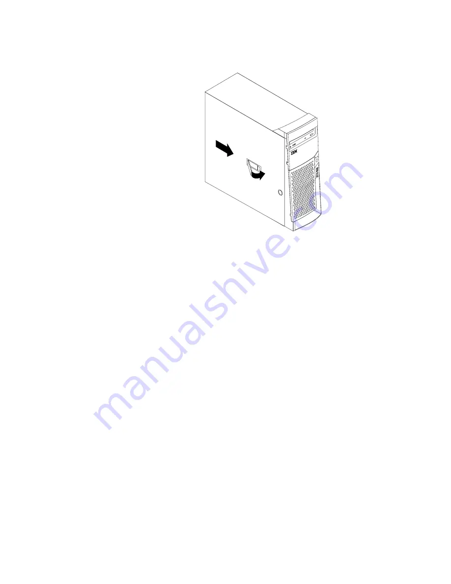
Position the cover on the chassis and slide the cover toward the front bezel of
the computer. Make sure to align the tabs on the computer with the cover.

4.

Close the cover-release latch to secure the cover in place.

5.

Reconnect the external cables and cords to the computer. See “Chapter 2.
Installing external options” on page 9 and the Quick Reference.

6.

To update the configuration, see “Chapter 4. Updating the computer
configuration” on page 31.

30

User Guide

Summary of Contents for NetWista A60 Type 6838

Page 1: ...NetVista User Guide A60 Type 6838 A60i Type 6848 ...

Page 2: ......

Page 3: ...NetVista User Guide A60 Type 6838 A60i Type 6848 ...

Page 4: ...ormation on page v and Appendix E Notices and trademarks on page 45 First Edition October 2000 Copyright International Business Machines Corporation 2000 All rights reserved US Government Users Restricted Rights Use duplication or disclosure restricted by GSA ADP Schedule Contract with IBM Corp ...

Page 5: ...ng parts on the system board 16 Installing memory 17 Installing adapters 19 Installing internal drives 21 Drive specifications 21 Power and signal cables for internal drives 22 Installing internal drives in bays 1 2 and 3 24 Installing internal drives in bays 4 5 6 and 7 25 Installing a security U bolt 28 Replacing the cover and connecting the cables 29 Chapter 4 Updating the computer configuratio...

Page 6: ...iv User Guide ...

Page 7: ...ll cables to devices 3 Attach signal cables to connectors 4 Attach power cords to outlet 5 Turn device ON To disconnect 1 Turn everything OFF 2 First remove power cords from outlet 3 Remove signal cables from connectors 4 Remove all cables from devices DANGER Le courant électrique provenant de l alimentation du téléphone et des câbles de transmission peut présenter un danger Pour éviter tout risqu...

Page 8: ...When replacing the battery use only IBM Part Number 33F8354 or an equivalent type battery recommended by the manufacturer The battery contains lithium and can explode if not properly used handled or disposed of Do not v Throw or immerse into water v Heat to more than 100 C 212 F v Repair or disassemble Dispose of the battery as required by local ordinances or regulations ATTENTION Danger d explosi...

Page 9: ...t un orage pour éviter tout risque de choc électrique utilisez toujours un téléphone sans fil v En cas de fuite de gaz n utilisez jamais un téléphone situé à proximité de la fuite Laser compliance statement Some IBM Personal Computer models are equipped from the factory with a CD ROM drive or a DVD ROM drive CD ROM drives and DVD ROM drives are also sold separately as options CD ROM drives and DVD...

Page 10: ... classe 1 conforme aux normes CEI 825 et CENELEC EN 60 825 Lorsqu une unité de CD ROM DVD ROM est installée tenez compte des remarques suivantes ATTENTION Pour éviter tout risque d exposition au rayon laser respectez les consignes de réglage et d utilisation des commandes ainsi que les procédures décrites L ouverture de l unité de CD ROM DVD ROM peut entraîner un risque d exposition au rayon laser...

Page 11: ...ovides instructions for removing the cover and installing hard disk drives memory and adapters in your computer v Chapter 4 Updating the computer configuration provides instructions for updating the computer configuration installing device drivers and erasing a lost or forgotten password v Appendix A Changing the battery provides instructions to help you change the battery if you need to v Appendi...

Page 12: ...your computer If you have Internet access the most up to date manuals for your computer are available from the World Wide Web To access this information point your browser to http www ibm com pc support Type your machine type and model number in the Quick Path field and click Go x User Guide ...

Page 13: ...y Information on page v These precautions and guidelines will help you work safely See Access IBM for general information about the use operation and maintenance of your computer Access IBM also contains information to help you solve problems and get repair service or other technical assistance Identifying your computer To properly install options you will need to know the model of your computer T...

Page 14: ...amic video memory technology v High performance accelerated graphics port AGP adapter Audio subsystem 16 bit integrated Sound Blaster Pro compatible audio subsystem Connectivity v 10 100 Mbps Ethernet adapter that supports the Wake on LAN features some models v Modem some models System management features v Remote Program Load RPL and Dynamic Host Configuration Protocol DHCP v Wake on LAN requires...

Page 15: ...ontrol v Security profile by device IBM preinstalled software Your computer might come with preinstalled software If it does an operating system device drivers to support built in features and other support programs are included Operating systems supported v Microsoft Windows Millennium Edition Me v Microsoft Windows 2000 Professional Operating systems tested for compatibility 1 v Microsoft Window...

Page 16: ...bo Linux Specifications This section lists the physical specifications for the NetVista computer Your computer has five 32 bit PCI expansion slots one AGP slot and seven drive bays Note The computer is classified as a Class A or Class B digital device See the Quick Reference for further information about this classification 4 User Guide ...

Page 17: ...heat output vary depending on the number and type of optional features installed and the power management optional features in use Heat output approximate in British thermal units Btu per hour Minimum configuration 240 Btu hr 75 watts Maximum configuration 940 Btu hr 275 watts Airflow Approximately 0 34 cubic meters per minute 12 cubic feet per minute maximum Acoustical noise emission values Avera...

Page 18: ...nformation by calling the following telephone numbers v Within the United States call 1 800 IBM 2YOU 1 800 426 2968 your IBM reseller or IBM marketing representative v Within Canada call 1 800 565 3344 or 1 800 465 7999 v Outside the United States and Canada contact your IBM reseller or IBM marketing representative Tools required To install some options in your computer you might need a flat blade...

Page 19: ... cover or other unpainted metal surface on the computer for at least two seconds This reduces static electricity in the package and your body v When possible remove the option and install it directly in the computer without setting the option down When this is not possible place the static protective package that the option came in on a smooth level surface and place the option on it v Do not plac...

Page 20: ...8 User Guide ...

Page 21: ...fy the required connector and then use the instructions that come with the option to help you make the connection and install any software or device drivers that are required for the option Important Before you install or remove any option read Safety Information on page v These precautions and guidelines will help you work safely Locating the connectors on the front of your computer The following...

Page 22: ...u to determine where to connect the cables on your computer Connector Description Mouse connector Used to attach a mouse trackball or other pointing device that uses a standard mouse connector Keyboard connector Used to attach a keyboard that uses a standard keyboard connector USB connectors Used to attach a device that requires a Universal Serial Bus USB connection such as a USB scanner or USB pr...

Page 23: ... external audio device a cable is connected between the audio line out connector of the device and the audio line in connector of the computer High performance video adapter Some models come with a high performance AGP video adapter Connector Description 1 S Video connector Used to attach a television set that has an S Video connector The S Video cable required to connect the television set to the...

Page 24: ...h an ADSL service provider Depending on how your home or office is wired the ADSL modem uses either wires 2 and 5 or wires 3 and 4 of the telephone line wall connector Refer to the label on the back of the ADSL modem and set the switch on the back of the ADSL modem to match the wiring scheme If you do not know which wiring scheme to use contact your ADSL service provider Home PNA network adapter S...

Page 25: ...more than one account Check your ISP access agreement for more information Obtaining device drivers You can obtain device drivers for operating systems that are not preinstalled at http www ibm com pc support on the World Wide Web Installation instructions are provided in README files with the device driver files Chapter 2 Installing external options 13 ...

Page 26: ...14 User Guide ...

Page 27: ... on page 6 before removing the cover To remove the cover 1 Shut down your operating system remove any media diskettes CDs or tapes from the drives and turn off all attached devices and the computer 2 Unplug all power cords from electrical outlets 3 Disconnect all cables attached to the computer This includes power cords input output I O cables and any other cables that are connected to the compute...

Page 28: ...To access the system board you must remove the computer cover For information on removing the computer cover see Removing the cover on page 15 You might need to remove adapters to access some components on the system board For information about adapters see Installing adapters on page 19 When disconnecting cables be sure to note where they are attached so you can correctly reattach them later Iden...

Page 29: ...r 10 Secondary IDE connector 22 PCI slot 11 Front USB connector 23 AGP slot 12 Front panel connector Installing memory Your computer has four connectors for Rambus in line memory modules RIMMs that provide up to a maximum of 2 GB of system memory The IBM installed RIMMs that come with your computer are ECC error checking and correction Rambus dynamic random access memory RDRAM modules When install...

Page 30: ...e slowest RIMM Removing a RIMM or C RIMM To remove a RIMM or C RIMM 1 To locate the RIMM connectors inside your computer see Identifying parts on the system board on page 16 2 At both ends of the RIMM connector on the system board push outward on the retaining clips until the module is loosened Lift the RIMM or C RIMM out of the connector Note Be careful not to push too hard on the retaining clips...

Page 31: ...ption go to the appropriate section v To complete the installation go to Replacing the cover and connecting the cables on page 29 Installing adapters This section provides information and instructions for installing and removing adapters Adapter slots Your computer has five expansion slots for peripheral component interconnect PCI adapters and one slot for an accelerated graphics port AGP adapter ...

Page 32: ...atch and the slot cover for the appropriate expansion slot 3 Remove the adapter from its static protective package 4 Install the adapter into the appropriate slot on the system board 5 Install the adapter slot cover latch 20 User Guide ...

Page 33: ... enable your computer to read other types of media Some of the different drives that are available for your computer are v Hard disk drives v Tape drives v CD drives or DVD drives v Removable media drives Internal drives are installed in bays Within this book the bays are referred to as bay 1 bay 2 and so on When you install an internal drive it is important to note what type and size of drive tha...

Page 34: ... drive 5 Bay 5 Maximum Height 25 4 mm 1 0 in Hard disk drive 6 Bay 6 Maximum Height 25 4 mm 1 0 in Hard disk drive 7 Bay 7 Maximum Height 25 4 mm 1 0 in Hard disk drive Notes 1 Drives that are greater than 41 3 mm 1 6 in high cannot be installed 2 Install removable media tape or CD drives in the accessible bays bay 1 or 2 Power and signal cables for internal drives Your computer uses cables to con...

Page 35: ... and change the connector that is used for the CD drive or DVD drive to the gray middle connector The narrower signal cable has two connectors for attaching the diskette drive to the diskette drive connector on the system board Note To locate connectors on the system board see Identifying parts on the system board on page 16 The following are some important points to remember when connecting power...

Page 36: ...Note If your computer has a CD drive or DVD drive you might need to remove the signal and power cables from the drive 2 Remove the bay panel and insert a flat blade screwdriver into one of the slots on the static shield in the drive bay into which you are installing the drive Gently pry the static shield loose from the drive bay 24 User Guide ...

Page 37: ...to do next v To work with another option go to the appropriate section v To complete the installation go to Replacing the cover and connecting the cables on page 29 Installing internal drives in bays 4 5 6 and 7 To install an internal drive in bay 4 5 6 or 7 1 Remove the cover see Removing the cover on page 15 Note If your computer has a CD drive or DVD drive you might need to remove the signal an...

Page 38: ...2 Remove the support bar by pulling it outward from the computer as shown 3 Pull and pivot the lower drive bay cage outward from the computer 26 User Guide ...

Page 39: ... sliding rails on the drive that you want to install and slide the drive along the rail guides into the unoccupied drive bay 5 Pivot the drive bay cage back into place Chapter 3 Installing internal options 27 ...

Page 40: ...nnected to the computer To install a U bolt 1 Remove cover see Removing the cover on page 15 2 Use a tool such as a screwdriver to remove the two metal knockouts 3 Insert the U bolt through the rear panel then attach and tighten the nuts with an appropriately sized or adjustable wrench 4 Replace the computer cover For more information see Replacing the cover and connecting the cables on page 29 5 ...

Page 41: ...ncluding power cords and telephone lines Also depending on the option that is installed you might need to confirm the updated information in the BIOS Setup Utility program To replace the cover and connect cables to your computer 1 Ensure that all components have been reassembled correctly and that no tools or loose screws are left inside your computer 2 Clear any cables that might impede the repla...

Page 42: ...the computer with the cover 4 Close the cover release latch to secure the cover in place 5 Reconnect the external cables and cords to the computer See Chapter 2 Installing external options on page 9 and the Quick Reference 6 To update the configuration see Chapter 4 Updating the computer configuration on page 31 30 User Guide ...

Page 43: ...nter 2 Select Exit Saving Changes and press Enter The computer will restart The Windows operating system will usually detect the new option update the configuration information and prompt you for device drivers if required Before installing any device drivers always check the documentation that is provided with your option for specific instructions Not all device drivers are installed in the same ...

Page 44: ...y manage the resources that are required by each device that is installed in the computer and to assign resources to new devices in a manner that avoids system conflicts Configuring startup devices When your computer is turned on it searches for an operating system The order in which it searches devices for the operating system is the startup sequence After adding new devices to the computer you m...

Page 45: ...11 Select Exit Saving Changes 12 Follow the directions on the screen Note You must remove the cover again to place the jumper to the normal setting Chapter 4 Updating the computer configuration 33 ...

Page 46: ...34 User Guide ...

Page 47: ...remove the cover See Removing the cover on page 15 3 Locate the battery Refer to the system board label inside your computer or see Identifying parts on the system board on page 16 4 If necessary remove any adapters that impede access to the battery See Installing adapters on page 19 for more information 5 Remove the old battery 6 Install the new battery 7 Replace any adapters that were removed to...

Page 48: ...36 User Guide ...

Page 49: ...are released they are available as downloadable files on the World Wide Web see the Quick Reference Instructions for using the system program updates are available in a README file that is included in the update files To update system programs flash the EEPROM 1 Insert a system program update flash diskette into the diskette drive drive A in your computer System program updates are available at ht...

Page 50: ...h diskette into drive A and turn on the computer and the monitor 12 After the update session is completed remove the diskette from the diskette drive and turn off the computer and monitor 13 Unplug the power cords from electrical outlets 14 Remove the cover See Removing the cover on page 15 15 Remove any adapters that impede access to the BIOS Configuration jumper 16 Replace the Clear CMOS Recover...

Page 51: ...896 KB C8000 DFFFF 96 KB PCI space available to adapter ROMs 896 K 1 MB E0000 FFFFF 128 KB System ROM BIOS main memory shadowed 1 MB 16 MB 1000000 FFFFFF 15 MB PCI space 16 MB 4096 MB 10000000 FFDFFFFF 4080 MB PCI space positive decode FFFE0000 FFFFFFFF 128 KB System ROM BIOS I O address map The following table lists resource assignments for the I O address map Any addresses that are not shown are...

Page 52: ...essor error register 00F1 016F 127 General I O locations available to PCI bus 0170 0177 8 Secondary IDE channel 01F0 01F7 8 Primary IDE channel 0200 0207 8 MIDI joystick port 0220 0227 8 Serial port 3 or 4 0228 0277 80 General I O locations available to PCI bus 0278 027F 8 LPT3 0280 02E7 102 Available 02E8 02EF 8 Serial port 3 or 4 02F8 02FF 8 COM2 0338 033F 8 Serial port 3 or 4 0340 036F 48 Avail...

Page 53: ... count register 00 15 Yes 0002 Channel 1 memory address register 00 15 Yes 0003 Channel 1 transfer count register 00 15 Yes 0004 Channel 2 memory address register 00 15 Yes 0005 Channel 2 transfer count register 00 15 Yes 0006 Channel 3 memory address register 00 15 Yes 0007 Channel 3 transfer count register 00 15 Yes 0008 Channels 0 3 read status write command register 00 07 0009 Channels 0 3 wri...

Page 54: ... memory address register 00 15 Yes 00CA Channel 6 transfer count register 00 15 Yes 00CC Channel 7 memory address register 00 15 Yes 00CE Channel 7 transfer count register 00 15 Yes 00D0 Channels 4 7 read status write command register 00 07 00D2 Channels 4 7 write request register 00 02 00D4 Channels 4 7 write single mask register bit 00 02 00D6 Channels 4 7 mode register write 00 07 00D8 Channels...

Page 55: ...present 6 Diskette controller 7 LPT1 8 Real time clock 9 Video ACPI 10 MIDI joystick some models only 11 Available to user 12 Mouse port 13 Math coprocessor 14 Primary IDE if present 15 Secondary IDE if present Note The default settings for COM 1 IRQ 4 COM 2 IRQ 3 and LPT 1 IRQ 7 can be changed to another IRQ Table 5 DMA channel assignment DMA channel Data width System resource 0 8 bits Open 1 8 b...

Page 56: ...44 User Guide ...

Page 57: ...OR IMPLIED INCLUDING BUT NOT LIMITED TO THE IMPLIED WARRANTIES OF NON INFRINGEMENT MERCHANTABILITY OR FITNESS FOR A PARTICULAR PURPOSE Some states do not allow disclaimer of express or implied warranties in certain transactions therefore this statement may not apply to you This information could include technical inaccuracies or typographical errors Changes are periodically made to the information...

Page 58: ...orporation in the United States or other countries or both IBM NetVista OS 2 Wake on LAN Pentium Intel MMX and AnyPoint are trademarks of Intel Corporation in the United States other countries or both Microsoft Windows and Windows NT are trademarks of Microsoft Corporation in the United States other countries or both Other company product and service names may be trademarks or service marks of oth...

Page 59: ...al 2 6 21 removable media 6 21 specifications 21 tape 21 E environment operating 5 I input output I O address map 39 41 DMA address map 41 features 2 installing internal drives 24 memory 17 RIMMs 18 security U bolt 28 installing adapters 19 installing options internal 15 system board 16 interrupt request IRQ channel assignments 43 L locating components 16 M memory installing 17 map 39 system 6 17 ...

Page 60: ...video continued controller 2 48 User Guide ...

Page 61: ......

Page 62: ... Part Number 06P8666 Printed in the United States of America on recycled paper containing 10 recovered post consumer fiber 1P P N 06P8666 ...

Reviews: