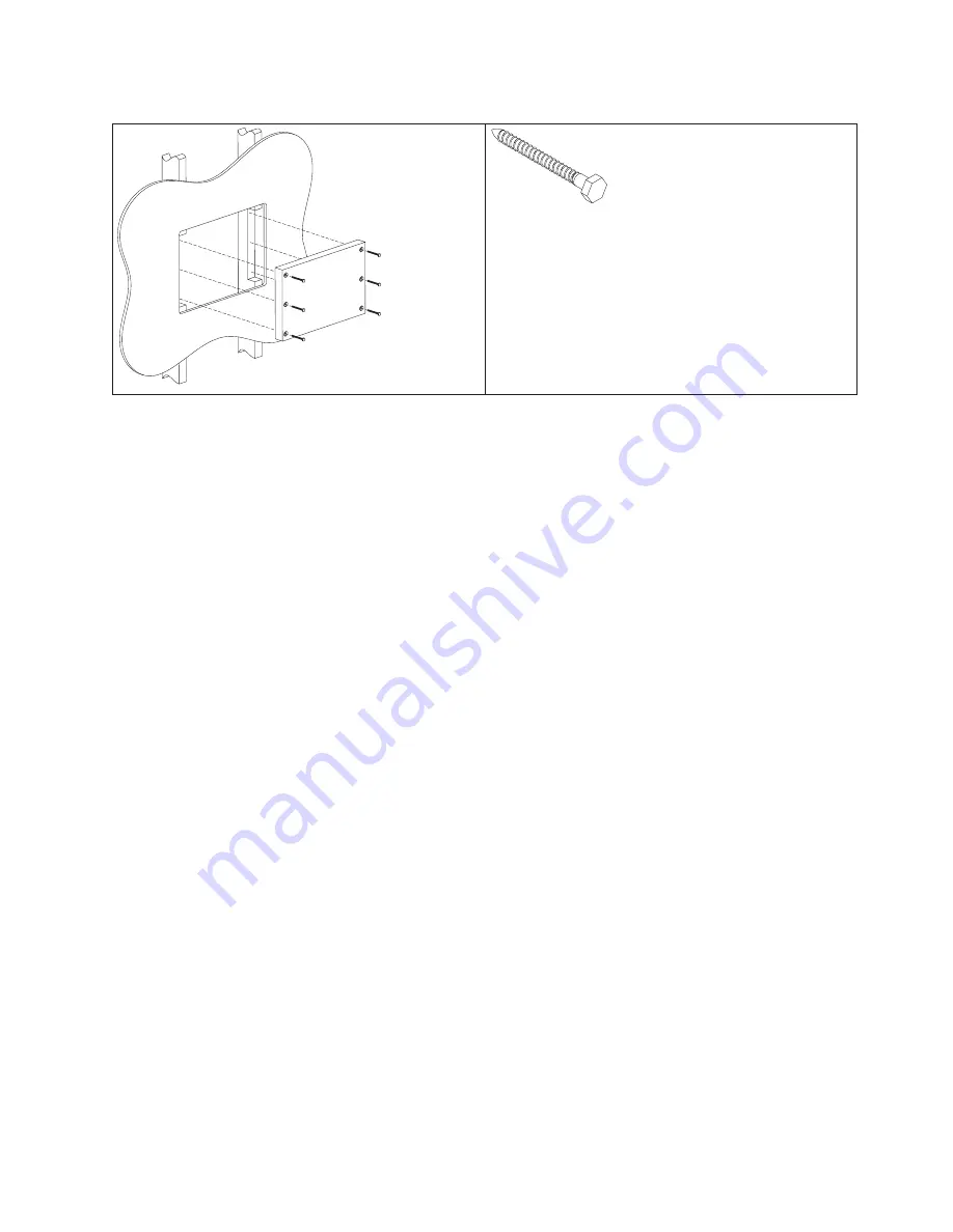
Table 8. Securing the wood support to the wood studs using lag screws
Lag screw
Screw size: 6.3 mm (0.25 in.) or nominal thread
diameter
Length: 60 mm (2.5 in.) minimum
Use a bubble level to assure that the wall mount plate is mounted squarely. Use six
wood screws to attach the wall mount plate to the wall. Center the wall mount
plate vertically on the wood support. Install the wood screws directly into the
wood support without pre-drilling a hole. Do not use soap or other lubricant on
the screws during installation. See “Fastener types” on page 33 for more
information.
After installation, make sure that the screw heads are flush or below the outer
surface of the wall mount plate. Check to make sure that you firmly and securely
attach the wall mount plate to the wall.
Method 2: Drywall surface
Use this method if you cannot make construction changes to the wall. This method
provides a safe attachment of the unit to the wall. However, there is risk that the
wall mount plate and unit might become loose if it is struck with a high force. The
drywall must be at least 12.7 mm (0.5 in.) thick to use this method. Use a bubble
level to assure that you mount the wall mount plate squarely.
Install two "Medium Duty" or "Heavy Duty" fasteners. Use fasteners, which are
designed for drywall, in one side of the wall mounting plate
B
, as shown in
Table 9 on page 32. Depending on the type of fastener, portions of the fastener can
be installed into the wall first. You can possibly thread them through the screw
holes in the wall mount plate. The recommended types of drywall fasteners are:
self-drilling drywall anchor, hollow wall anchor, toggle bolt, self-drilling drywall
toggle bolt, and plastic toggle bolt. Use two wood screws
A
, as shown in Table 9
on page 32, to attach the wall mount plate to the stud. Install the Wood Screws
directly into the center of the stud without pre-drilling a hole. Do not use soap or
other lubricant on the screws during installation. See “Fastener types” on page 33
fastener descriptions and pictures at the end of this section for more information.
Mounting the IBM AnyPlace Kiosk to the wall
Chapter 3. Mounting the IBM AnyPlace Kiosk to the wall
31
Summary of Contents for Models 5
Page 2: ......
Page 10: ...viii IBM AnyPlace Kiosk 4838...
Page 12: ...x IBM AnyPlace Kiosk 4838...
Page 20: ...8 IBM AnyPlace Kiosk 4838...
Page 38: ...Installing the IBM AnyPlace Kiosk 26 IBM AnyPlace Kiosk 4838...
Page 46: ...Mounting the IBM AnyPlace Kiosk to the wall 34 IBM AnyPlace Kiosk 4838...
Page 74: ...Removing and replacing FRUs 62 IBM AnyPlace Kiosk 4838...
Page 87: ...Appendix A Field replaceable units Copyright IBM Corp 2007 2008 75...
Page 92: ...Field replaceable units 80 IBM AnyPlace Kiosk 4838...
Page 114: ...IBM IBM GA27 4004 GA27 4004 Safety information 102 IBM AnyPlace Kiosk 4838...
Page 116: ...Safety information 104 IBM AnyPlace Kiosk 4838...
Page 127: ...Kiosk notices Appendix E Kiosk notices 115...
Page 128: ...Croatia wireless certification documents Kiosk notices 116 IBM AnyPlace Kiosk 4838...
Page 129: ...Kiosk notices Appendix E Kiosk notices 117...
Page 130: ...Kiosk notices 118 IBM AnyPlace Kiosk 4838...
Page 138: ...126 IBM AnyPlace Kiosk 4838...
Page 142: ...130 IBM AnyPlace Kiosk 4838...
Page 145: ......
Page 146: ...GA27 4369 01...


