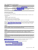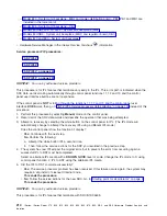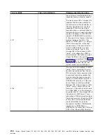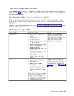
3.
Review
the
display
panels
on
the
system
unit
and
all
attached
expansion
units
and
I/O
towers.
The
lamp
test
is
only
active
on
the
expansion
units
and
I/O
towers
for
25
seconds
after
you
press
Enter
.
Are
all
of
the
following
lights
on
for
the
system
unit
and
all
attached
expansion
units
and
I/O
towers?
v
Power-on
light
v
Attention
light
v
A
five-by-seven
dot
pattern
for
the
8
or
32
character
display
as
installed
–
No
:
Exchange
the
following
FRUs
in
the
failing
unit
one
at
a
time
(see
-
Control
panel
(see
symbolic
FRU
-
Tower
card
(see
symbolic
FRU
-
Control
panel
cable
This
ends
the
procedure.
–
Yes
:
These
control
panel
lights
are
working
correctly.
Continue
with
the
next
step.
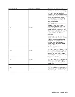
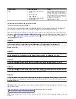
4.
Are
there
any
abnormal
characters
or
character
patterns
that
are
not
SRCs
or
normal
display
mode
displayed?
v
No
:
This
ends
the
procedure.
v
Yes
:
Exchange
the
following
FRUs
in
the
failing
unit
one
at
a
time
(see
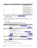
a.
Control
panel
(see
symbolic
FRU
b.
Tower
card
(see
symbolic
FRU
c.
Control
panel
cable
This
ends
the
procedure.
SPCN
PIP21:
For
use
by
authorized
service
providers.
Use
this
procedure
to
verify
that
the
Remote
Control
Panel
is
operating
correctly.
1.
If
the
system
has
logical
partitions,
perform
this
procedure
from
the
Primary
partition’s
console
and
the
system
control
panel.
To
determine
if
the
system
has
logical
partitions,
go
to
before
continuing
with
this
procedure.
2.
Select
function
04
Lamp
Test
on
the
control
panel
and
press
Enter
.
3.
Review
the
display
panels
on
the
system
unit.
Are
all
of
the
following
lights
on?
v
Power-on
light
v
Attention
light
v
Manual
light
v
Normal
light
v
Auto
light
v
Secure
light
v
The
8
character
display
segments
–
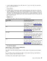
No
:
Exchange
the
following
FRU
in
the
failing
unit
-
Remote
Control
Panel
cable
-
04N5592
-
Operations
Console
Configuration
cable
—
97H7557
This
ends
the
procedure.
–
Yes
:
The
control
panel
lights
are
working
correctly.
This
ends
the
procedure.
Analyze
hardware
problems
223

