Configuration of IP-Forwarding Media Cards
137
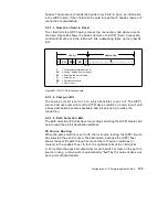
4.5.1.6 Direction Bit
HIPPI hosts set the direction bit (D). This bit determines how a switch or
router reads the 24-bits of destination address information. Figure 49 on page
135 and the previous descriptions of source routing and logical addressing
have the destination address information organized as if the host has set the
destination bit to 0.
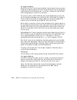
If the destination bit is set to 1, the information in the 24-bit destination
addressing is read starting from the left, and the logical addresses of host A
and B change places. The destination bit makes it easy for source and
destination hosts to reply and reverse transfer data to one another, or it can
serve as a means to trace where a connection originates.
4.5.1.7 L, VU, and W Bits
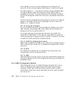
The L and VU control bits are not used by the GRF, and the HIPPI media
cards do not support double-wide HIPPI connections.
It will reject the connection if the W bit is set on.
4.5.1.8 IP Routing
In an IP connection, data coming from a HIPPI I/O channel is formatted into
standard IP packets. Embedded in the front of each IP datagram is the IP
header. The media card reads the header only if the information in the HIPPI
I-field indicates an IP connection.
The header contains the Internet address of the host sending the datagram
and the Internet address of the target IP media host for which the datagram is
intended. This target host can be attached to any media that supports IP, or
be reached via that attached media. Because the GRF is a router, it creates
and updates an IP routing table that describes paths to destination
addresses. This is the basis of IP routing.
Each GRF media card holds a copy of this IP routing table. When processing
an IP connection, a HIPPI media card “opens” the datagram’s header, reads
the address of the target host, and decides to which GRF media card the IP
datagram is transferred.
4.5.1.9 IP Routing and the I-field
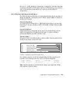
A HIPPI host’s I-field table can be used to direct the GRF HIPPI media card to
do IP routing.
In the I-field, the PS bit needs to be set to 01 or 11 and a designated
destination logical address (
0xfc0
) must be placed in bits 0–11. The mapping
Summary of Contents for IBM 9077
Page 2: ......
Page 18: ...xvi IBM 9077 SP Switch Router Get Connected to the SP Switch ...
Page 19: ... Copyright IBM Corp 1998 1 Part 1 Introducing and Installing the GRF ...
Page 20: ...2 IBM 9077 SP Switch Router Get Connected to the SP Switch ...
Page 86: ...68 IBM 9077 SP Switch Router Get Connected to the SP Switch ...
Page 122: ...Installation and Configuration 104 ...
Page 174: ...156 IBM 9077 SP Switch Router Get Connected to the SP Switch ...
Page 220: ...202 IBM 9077 SP Switch Router Get Connected to the SP Switch ...
Page 278: ...260 IBM 9077 SP Switch Router Get Connected to the SP Switch ...
Page 322: ...304 IBM 9077 SP Switch Router Get Connected to the SP Switch ...
Page 326: ...308 IBM 9077 SP Switch Router Get Connected to the SP Switch ...
Page 332: ...314 IBM 9077 SP Switch Router Get Connected to the SP Switch ...


