background image

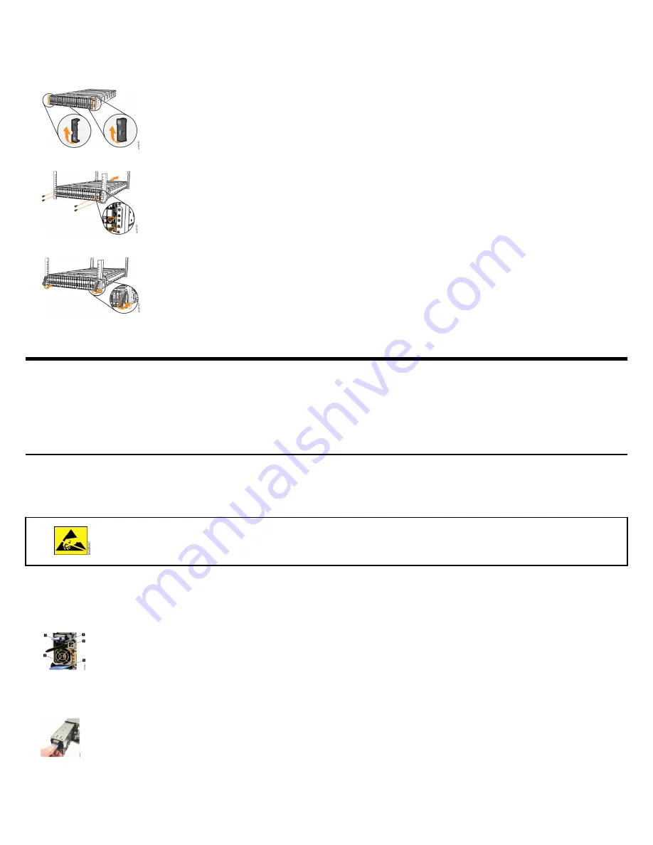
6. Secure the rear of the rail to the rear rack flange with two black M5 screws (5).
7. Repeat Step 

1

 on page 2 through Step 

6

 on page 3 to secure the opposite rail to the rack cabinet.

8. Remove each end cap from the front of the enclosure. Lift the bottom of each end cap

9. At the front of the enclosure, use two rack mounting screws to secure each side of the enclosure to the rack.

10.Reinstall the left and right end caps to the front of the enclosure.

Removing and replacing parts

If three persons or a lift are not available to install the control enclosure , the weight of the control enclosure must be reduced before it can

be safely lifted. Follow the procedures to remove several parts of thecontrol enclosure . Reinstall the parts after the control enclosure is

installed in the rack. If you did not remove any parts, continue to 

Connecting SAS cables

 on page 5.

Removing and replacing a power supply unit

To reduce weight during the installation procedure, you must remove and replace the power supply units (PSUs) in a control enclosure .

When the system is running, the redundant PSUs operate in parallel; one PSU continues to provide power if the other PSU fails.

About this task

Follow recommended procedures for handling electrostatic discharge (ESD)-sensitive devices.

No tools are required to complete this task. Do not remove or loosen any screws.

Do not insert a PSU if the PSU slot does not contain a power interposer.

Procedure
1. 
Fold out the handle (3) so that it extends perpendicular to the PSU.

1 Cable retention clip
2 LED indicator
3 PSU handle
4 PSU release tab
5 Power interposer release tab

2. Hold the PSU handle and press the PSU release tab (4). Steadily pull the handle horizontally to slide the PSU from the control enclosure .

Support the PSU with your other hand as it is released.

3. To replace the PSU, fold out the handle so that it extends perpendicular to the PSU.
4. Extend the PSU handle and support the PSU. Slide the PSU into the control enclosure until the release tab engages with a "click".

3

Summary of Contents for FlashSystem 7200

Page 1: ...ms are available Philips screw driver Box knife Flat blade screw driver optional Three Ethernet cables The control enclosure and the following related parts are included in one box The enclosed invent...

Page 2: ...a power supply unit on page 3 10 Record the last 6 digits of the serial number on the back of each PSU then set the power supplies aside Item Left PSU Right PSU Serial Number 11 Remove the upper and...

Page 3: ...t To reduce weight during the installation procedure you must remove and replace the power supply units PSUs in a control enclosure When the system is running the redundant PSUs operate in parallel on...

Page 4: ...lifting platform or other nearby surface to support the node canister as it is extracted from the control enclosure 4 Hold the node canister by its sides so that it is level and its weight is balanced...

Page 5: ...nclosure 2 To add a second expansion enclosure chain to the control enclosure complete the following steps a Connect SAS port 3 of the top node canister in the control enclosure to SAS port 1 of the l...

Page 6: ...system 32 Gbps FC 4 0 3 Supports simultaneous SCSI and NVMeFC connections on the same port 25 Gbps Ethernet iWARP 2 0 3 Supports iSCSI or iSER host attachment 25 Gbps Ethernet RoCE 2 0 3 12 Gbps SAS...

Page 7: ...erwise continue to Setting up the system on page 7 Setting up the system Each node canister in the control enclosure has a 1 Gbps Ethernet technician port Before you initiate a new system you must con...

Page 8: ...ort Release ESR 78 2 0 Microsoft Edge 85 0 Google Chrome 85 0 JavaScript Cookies Scripts allowed to disable or replace context menus Mozilla Firefox only In addition review the following consideration...

Page 9: ...ernet cable from Ethernet port 2 on the node to canister your Ethernet network Port 2 can be used for the management GUI and for iSCSI host attachment Ethernet ports 3 and 4 are for iSCSI attachment o...

Page 10: ...net mask Gateway VLAN ID FlashSystem 7200 Fibre Channel connections Each node canister supports 4 port 32 Gbps Fibre Channel FC adapters or 4 port 16 Gbps FC adapters Install the FC networking adapter...

Page 11: ...to the following guidelines Then record the FC port connections in the following table Install the first FC adapter in adapter slot 1 Install the second FC adapter if applicable in adapter slot 2 Ada...

Page 12: ...c Click the documentation link Environmental notices This information contains all the required environmental notices for IBM Systems products in English and other languages The IBM Systems Environme...

Page 13: ...atents You can send license inquiries in writing to IBM Director of Licensing IBM Corporation North Castle Drive Armonk NY 10504 1785 U S A For license inquiries regarding double byte character set DB...

Page 14: ...bute these sample programs in any form without payment to IBM for the purposes of developing using marketing or distributing application programs conforming to the application programming interface fo...

Page 15: ...ohne Zustimmung von IBM ver ndert bzw wenn Erweiterungskomponenten von Fremdherstellern ohne Empfehlung von IBM gesteckt eingebaut werden EN 55032 Klasse A Ger te m ssen mit folgendem Warnhinweis vers...

Page 16: ...atement applies to products greater than 20 A per phase three phase Japan Voluntary Control Council for Interference VCCI Notice Korea Notice People s Republic of China Notice Russia Notice Taiwan Not...

Page 17: ...is not responsible for any radio or television interference caused by using other than recommended cables and connectors or by unauthorized changes or modifications to this equipment Unauthorized cha...

Reviews: