background image

DANGER

When working on or around the system, observe the following precautions:

Electrical voltage and current from power, telephone, and communication cables are hazardous. To
avoid a shock hazard:

v

If IBM supplied the power cord(s), connect power to this unit only with the IBM provided power
cord. Do not use the IBM provided power cord for any other product.

v

Do not open or service any power supply assembly.

v

Do not connect or disconnect any cables or perform installation, maintenance, or reconfiguration
of this product during an electrical storm.

v

The product might be equipped with multiple power cords. To remove all hazardous voltages,
disconnect all power cords.

v

Connect all power cords to a properly wired and grounded electrical outlet. Ensure that the outlet
supplies proper voltage and phase rotation according to the system rating plate.

v

Connect any equipment that will be attached to this product to properly wired outlets.

v

When possible, use one hand only to connect or disconnect signal cables.

v

Never turn on any equipment when there is evidence of fire, water, or structural damage.

v

Do not attempt to switch on power to the machine until all possible unsafe conditions are
corrected.

v

Assume that an electrical safety hazard is present. Perform all continuity, grounding, and power
checks specified during the subsystem installation procedures to ensure that the machine meets
safety requirements.

v

Do not continue with the inspection if any unsafe conditions are present.

v

Disconnect the attached power cords, telecommunications systems, networks, and modems before
you open the device covers, unless instructed otherwise in the installation and configuration
procedures.

v

Connect and disconnect cables as described in the following procedures when installing, moving,
or opening covers on this product or attached devices.

To Disconnect:

1.

Turn off everything (unless instructed otherwise).

2.

Remove the power cords from the outlets.

3.

Remove the signal cables from the connectors.

4.

Remove all cables from the devices.

To Connect:

1.

Turn off everything (unless instructed otherwise).

2.

Attach all cables to the devices.

3.

Attach the signal cables to the connectors.

4.

Attach the power cords to the outlets.

5.

Turn on the devices.

Sharp edges, corners and joints may be present in and around the system. Use care when
handling equipment to avoid cuts, scrapes and pinching.

(D005)

(R001 part 1 of 2)

:

DANGER:

Observe the following precautions when working on or around your IT rack system:

v

Heavy equipment–personal injury or equipment damage might result if mishandled.

v

Always lower the leveling pads on the rack cabinet.

v

Always install stabilizer brackets on the rack cabinet.

v

To avoid hazardous conditions due to uneven mechanical loading, always install the heaviest devices
in the bottom of the rack cabinet. Always install servers and optional devices starting from the bottom
of the rack cabinet.

vi

Power Systems: Installing the IBM Power System E850C (8408-44E)

Summary of Contents for E850C

Page 1: ...Power Systems Installing the IBM Power System E850C 8408 44E GI11 9920 00 IBM...

Page 2: ......

Page 3: ...Power Systems Installing the IBM Power System E850C 8408 44E GI11 9920 00 IBM...

Page 4: ...y Notices manual G229 9054 and the IBM Environmental Notices and User Guide Z125 5823 This edition applies to IBM Power Systems servers that contain the POWER8 processor and to all associated models C...

Page 5: ...e server with keyboard video and mouse 22 Cabling the server and connecting expansion units 23 Completing the server setup 23 Completing the server setup by using an HMC 23 Completing the server setup...

Page 6: ...iv Power Systems Installing the IBM Power System E850C 8408 44E...

Page 7: ...oduct The documentation contains the safety information in your national language with references to the U S English source Before using a U S English publication to install operate or service this pr...

Page 8: ...chine meets safety requirements v Do not continue with the inspection if any unsafe conditions are present v Disconnect the attached power cords telecommunications systems networks and modems before y...

Page 9: ...t temperature for all your rack mounted devices v Do not install a unit in a rack where the air flow is compromised Ensure that air flow is not blocked or reduced on any side front or back of a unit u...

Page 10: ...potential hazards v Verify that the route that you choose can support the weight of the loaded rack cabinet Refer to the documentation that comes with your rack cabinet for the weight of a loaded rac...

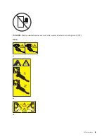
Page 11: ...DANGER Rack mounted devices are not to be used as shelves or work spaces L002 L003 or or 1 2 3 4 or Safety notices ix...

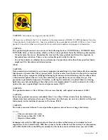
Page 12: ...cords The product might be equipped with multiple power cords To remove all hazardous voltages disconnect all power cords L003 L007 CAUTION A hot surface nearby L007 L008 x Power Systems Installing th...

Page 13: ...tacle Although shining light into one end and looking into the other end of a disconnected optical fiber to verify the continuity of optic fibers many not injure the eye this procedure is potentially...

Page 14: ...lean Keep riser tilt option flat at all times except for final minor adjustment when needed v Do not stand under overhanging load v Do not use on uneven surface incline or decline major ramps v Do no...

Page 15: ...interfaces that connect to the OSP outside plant or its wiring These interfaces are designed for use as intrabuilding interfaces only Type 2 or Type 4 ports as described in GR 1089 CORE and require i...

Page 16: ...xiv Power Systems Installing the IBM Power System E850C 8408 44E...

Page 17: ...p v Rack with four Electronic Industries Association EIA units 4U of space You also need one of the following consoles v Hardware Management Console HMC Version 8 Release 8 6 0 or later v Graphics mon...

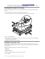
Page 18: ...with the six pins on the chassis and then lift the handle up B until the latches click into place 3 Repeat these steps for all four lift handles Installing the server into a rack You must remove compo...

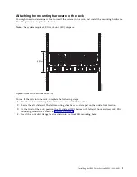
Page 19: ...ng steps 1 Use the rack mount template to determine and mark the location 2 Locate the left slide rail The left mounting slide has an L stamped on the inside front location 3 At the front of the rack...

Page 20: ...ol to secure the slam latch bracket to the front rail flange with one M5 X 16 mm torx socket pan head screw A placed in the middle hole 1b of the EIA rack unit as shown in Figure 3 8 Repeat steps 2 on...

Page 21: ...so that it is easier to lift Attention v Attach an electrostatic discharge ESD wrist strap to an unpainted metal surface of your hardware to prevent the electrostatic discharge from damaging your har...

Page 22: ...system as shown in Figure 5 Removing the front cover Learn how to remove the front cover To remove the front cover complete the following steps 1 Go to the front of the system chassis 2 Place your fin...

Page 23: ...to remove the system fans To remove the system fans complete the following steps 1 Rotate the fan handle A in the direction that is shown in Figure 7 on page 8 to unlock the fan from its slot Figure 6...

Page 24: ...system fans Removing the disk drive backplane Learn how to remove the disk drive backplane To remove the disk drive backplane complete the following steps 1 Use the included 4 mm Allen hand tool to lo...

Page 25: ...umbscrews on the RAID assembly to loosen them as shown in Figure 9 3 Pull out the latches and remove the disk drive backplane from the system Figure 8 Loosening the captive shipping screws Figure 9 Re...

Page 26: ...ndle up B until the latches click into place 3 Repeat these steps for all four lift handles Installing the system into the rack Use the procedure in this section to install the system into the rack Th...

Page 27: ...as shown in Figure 11 5 Tilt the front of the system down so that the chassis pins are inserted into the front 4 and 5 and middle holes in the mounting hardware as shown in Figure 11 6 Remove the lif...

Page 28: ...ncrease or decrease your risk of receiving electric shock when using or working on electrical equipment v If you do not have an ESD wrist strap just prior to removing the product from ESD packaging an...

Page 29: ...rack Ensure that the fan handle A is rotated open in the direction as shown in Figure 14 on page 14 2 Using your hand to support the bottom of the fan align the fan with the fan slot and slide it int...

Page 30: ...mplete the following steps 1 Move to the front of the rack 2 Position the cover A on the front of the system unit so that the four pins on the system match the four holes on the rear of the cover Figu...

Page 31: ...s 1 Ensure that you have the electrostatic discharge ESD wrist strap attached If not attach it now 2 Move to the rear of the rack 3 Align the power supply A with the bay and slide the power supply int...

Page 32: ...rm complete the following steps 1 Attach the inner plate A to the system chassis by hand tightening the two captive screws B through the threaded holes on the chassis as shown in Figure 17 on page 17...

Page 33: ...nut clips C to the rack rail in the location where you are attaching the outer plate to the rail as shown in Figure 18 Figure 17 Attaching the inner plate to the system chassis Figure 18 Attaching the...

Page 34: ...e consoles that are available Go to the instructions for the applicable console interface or terminal in the following table Table 1 Available console types Console type Operating system Logical parti...

Page 35: ...r complete the following steps 1 Using a serial cable that is equipped with a null modem connect the ASCII terminal to the serial port on the rear of the server 2 Complete the following steps a Plug t...

Page 36: ...of capacity on demand Using service applications the HMC can also communicate with managed systems to detect consolidate and forward information to IBM service for analysis If you have not installed a...

Page 37: ...the Ethernet port that is labeled HMC2 T5 on the managed server 4 Continue with Cabling the server and connecting expansion units on page 23 Cabling the server and accessing the IVM When you install...

Page 38: ...the optical device and press Enter f Select Normal Boot and confirm that you want to exit SMS 5 Install the Virtual I O Server a Select the console and press Enter b Select a language for the BOS men...

Page 39: ...flashing check the power cord connections 2 If you have an expansion unit that you need to install install it now For information about connecting enclosures and expansion units see Enclosures and exp...

Page 40: ...ng the administrator user ID and password f Select System Config Time of Day g Adjust the time of day h Select Save Settings If you are using an HMC Enhanced interface complete the following steps a I...

Page 41: ...knowledgecenter POWER8 p8efc p8efc_accessing_template_library htm v If you have existing partitions on another system you can capture those configurations save it to the template library and deploy t...

Page 42: ...tem is being started c The power on light on the control panel stops flashing and remains on indicating that the system is powered on For instructions see Starting a system that is not managed by an H...

Page 43: ...tes for the HMC with an Internet connection http www ibm com support knowledgecenter POWER8 p8hai area3fixeshmc htm Consider the following prerequisites before you install the server 1 Ensure that you...

Page 44: ...ive enclosure or expansion drawer that came preinstalled in this rack use the documentation supplied with these options For information about connecting enclosures and expansion units see Enclosures a...

Page 45: ...that are available Go to the instructions for the applicable console interface or terminal in the following table Table 3 Available console types Console type Operating system Logical partitions Cabl...

Page 46: ...ons htm To cable an ASCII terminal to the server complete the following steps 1 Using a serial cable that is equipped with a null modem connect the ASCII terminal to the serial port on the rear of the...

Page 47: ...eps 1 In the navigation area click Updates 2 In the work area view and record the information that appears in the HMC Code Level section including the HMC version release Service Pack build level and...

Page 48: ...ervice provider authority in ASMI b Using the Web based ASMI change the following settings as appropriate for the type of partition on which you are installing the Integrated Virtualization Manager Fo...

Page 49: ...4 Power on the console 5 Continue with Cabling the server and connecting expansion units on page 23 Routing cables through the cable management arm and connecting expansion units Use this procedure t...

Page 50: ...for the managed system by using the HMC Enhanced interface see Setting passwords for the managed system http www ibm com support knowledgecenter POWER8 p8hai p8hai_setpassword_enh htm 2 Update the tim...

Page 51: ...on screen instructions If you are using an HMC Enhanced interface complete the following steps a In the navigation area click the Resources icon and then select All Systems b In the content pane selec...

Page 52: ...evel of server firmware in the upper right corner under the copyright statement c Update the time of day In the navigation area expand System Configuration d Click Time of Day The content pane display...

Page 53: ...ibm com support knowledgecenter POWER8 p8ha5 fix_firm_no_hmc_aix htm v If you are using VIOS see Updating the Virtual I O Server s firmware and device microcode with an Internet connection http www ib...

Page 54: ...38 Power Systems Installing the IBM Power System E850C 8408 44E...

Page 55: ...herefore this statement may not apply to you This information could include technical inaccuracies or typographical errors Changes are periodically made to the information herein these changes will be...

Page 56: ...a in sensitive or critical operations Users should periodically check IBM s support websites for updated information and fixes applicable to the system and related software Homologation statement This...

Page 57: ...www ibm com able Privacy policy considerations IBM Software products including software as a service solutions Software Offerings may use cookies or other technologies to collect product usage inform...

Page 58: ...ent in a residential area is likely to cause harmful interference in which case the user will be required to correct the interference at his own expense Properly shielded and grounded cables and conne...

Page 59: ...on the standard of the VCCI Council If this equipment is used in a domestic environment radio interference may occur in which case the user may be required to take corrective actions Japan Electronics...

Page 60: ...lic of China Declaration This is a Class A product In a domestic environment this product may cause radio interference in which case the user may need to perform practical action Electromagnetic Inter...

Page 61: ...ngeschlossen werden IBM bernimmt keine Verantwortung f r die Einhaltung der Schutzanforderungen wenn das Produkt ohne Zustimmung von IBM ver ndert bzw wenn Erweiterungskomponenten von Fremdherstellern...

Page 62: ...and found to comply with the limits for a Class B digital device pursuant to Part 15 of the FCC Rules These limits are designed to provide reasonable protection against harmful interference in a resid...

Page 63: ...l num rique de la classe B est conforme la norme NMB 003 du Canada European Community Compliance Statement This product is in conformity with the protection requirements of EU Council Directive 2014 3...

Page 64: ...ent for products greater than 20 A single phase This statement explains the JEITA statement for products greater than 20 A per phase three phase IBM Taiwan Contact Information 48 Power Systems Install...

Page 65: ...den Deutschland Einhaltung des Gesetzes ber die elektromagnetische Vertr glichkeit von Ger ten Dieses Produkt entspricht dem Gesetz ber die elektromagnetische Vertr glichkeit von Ger ten EMVG Dies ist...

Page 66: ...the express consent of IBM Rights Except as expressly granted in this permission no other permissions licenses or rights are granted either express or implied to the publications or any information da...

Page 67: ...Notices 51...

Page 68: ...IBM Part Number 29R2425 Printed in USA GI11 9920 00 1P P N 29R2425...

Reviews: