background image


  4.

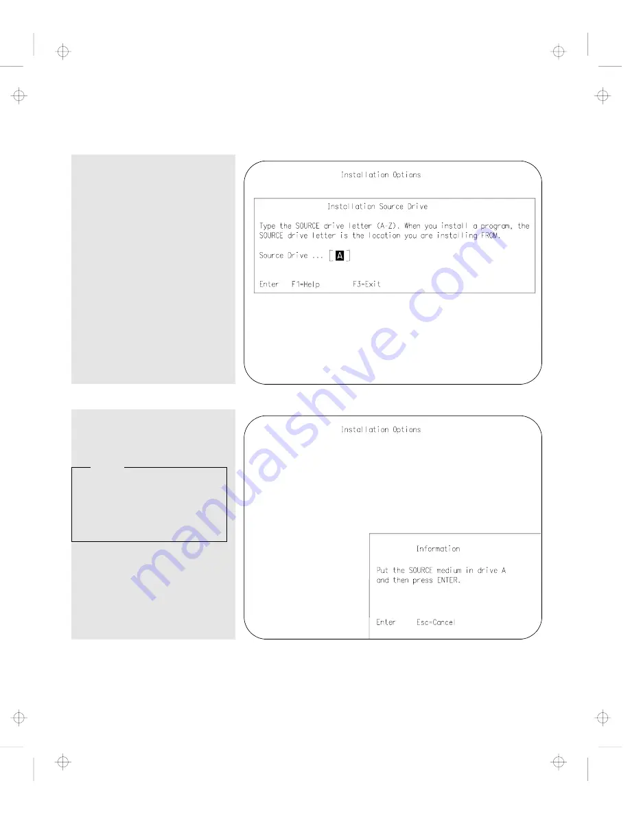
Insert the Dock I Option
Diskette into drive A. At the
operating system prompt, type

UINSTALL

 and press Enter. This

screen appears.

  5.

Press Enter. This screen
appears.

  Note 

The reference to “SOURCE
medium” on this screen
means the Dock I Option
Diskette.


Chapter 5. Using the SCSI Controller and Support Software

5-11

Title: C74AMST CreationDate: 06/23/93 17:09:07

Summary of Contents for Dock I

Page 1: ...IBM ThinkPad Dock I User s Guide Title C74AMST CreationDate 06 23 93 17 09 07...

Page 2: ...Title C74AMST CreationDate 06 23 93 17 09 07...

Page 3: ...IBM ThinkPad Dock I User s Guide Title C74AMST CreationDate 06 23 93 17 09 07...

Page 4: ...ssible that this publication may contain reference to or information about IBM products machines and programs programming or services that are not announced in your country Such references or informat...

Page 5: ...witch Power is controlled by the computer s power switch For emergencies always use easily accessible electrical outlets to turn off the power by unplugging the Dock I power cord D A N G E R To avoid...

Page 6: ...skyddsklensp nningsutg ngen ansluts till ett n t som passerar s v l ojordad som jordad milj Jordet stikkontakt skal benyttes n r apparatet tilkoples datanett Laite on liitett v suojakosketinspistoras...

Page 7: ...r t e le p h o n e a n d c o m m u n ic a t io n c a b le s is h a z a r d o u s To a v o id s h o c k h a z a r d c o n n e c t a n d d is c o n n e c t c a b le s a s s h o w n b e lo w w h e n in s...

Page 8: ...vi IBM ThinkPad Dock I User s Guide Title C74AMST CreationDate 06 23 93 17 09 07...

Page 9: ...e installation of the option device drivers and the SCSI diagnostics utility program Chapter 6 Solving Problems describes how you can detect and resolve Dock I problems Appendix A Starting up the OS f...

Page 10: ...trademarks service marks FCC statement CDCC statement and EC directive conformance statement viii IBM ThinkPad Dock I User s Guide Title C74AMST CreationDate 06 23 93 17 09 07...

Page 11: ...r 2 10 Using the Display Stand 2 13 Carrying the Dock I with the Computer Attached 2 14 Chapter 3 Using the Security Features 3 1 Using the Security Lock 3 2 Security Lock Description 3 2 Key Position...

Page 12: ...roller and Support Software 5 1 Setting up the SCSI Controller Configuration 5 3 Default Settings 5 3 SCSI Controller s Memory Address Settings 5 5 SCSI Controller s Interrupt Settings 5 5 SCSI ID 5 6...

Page 13: ...ndix B SCSI Information B 1 Device Ordering and the Boot Drive B 2 External SCSI Connector B 2 Internal SCSI Connector B 3 Termination B 4 SCSI Cable Length Specifications B 4 Appendix C Using the Sel...

Page 14: ...E 6 Canadian Department of Communications Compliance Statement E 6 Avis de conformit aux normes du minist re des Communications du Canada E 6 European Community EC Directive Conformance Statement E 7...

Page 15: ...Dock I has enhanced security features to protect it from being used by unauthorized persons The following summarizes the standard features or options on the Dock I Multimedia Oriented Features Audio a...

Page 16: ...size or half size AT bus 16 bit slot A less than 1 inch high drive location for an internal storage device An internal and external SCSI device connectors 1 2 IBM ThinkPad Dock I User s Guide Title C7...

Page 17: ...representative or dealer Dock I Manual Option Diskette Power Cord Security Lock Keys Notes 1 An extra key is provided as a spare 2 The key number is necessary when replacing lost keys See Ordering Ad...

Page 18: ...ctor The docking connector male type 240 pin fits into the system expansion connector 3 Lever Cover This cover is used to prevent the locking lever on the computer from being slid inward the hard disk...

Page 19: ...rotrudes from the Dock I snapping it closed secures the computer by engaging the computer with the hooks 14 Sliding the slide knob 11 to the left snaps the release lock lever open 1 Security Lock The...

Page 20: ...al stereo speakers use this jack with the audio out right jack 11 through an amplifier 5 Speaker In Left Jack The speaker in left jack left input sound 2 pin connects the speaker in left plug of the a...

Page 21: ...ideo in connector 8 1 Speaker In Right Jack The speaker in right jack right input sound 2 pin connects the speaker in right plug of the audio cable Use this jack with the speaker in left jack 5 for st...

Page 22: ...ic keypad cable Important 1 Use this connector if you use an external keyboard or a numeric keypad 2 The keyboard numeric keypad on the computer cannot be used when the external keyboard external nume...

Page 23: ...below it The following figure and table show the name color and meaning of each LED indicator Symbol Name of LED Indicator LED Color Meaning 1 Docked Green Turns on when the computer has been correct...

Page 24: ...that is in suspend mode to a Dock I 4 PC Card In Use Orange Turns on when an inserted PC card PCMCIA card is accessed 5 Diskette Drive In Use Orange Turns on when the diskette drive in the computer is...

Page 25: ...pt this However you can enter suspend and standby modes The following table summarizes these conditions Attempt to Enter Can the Computer Enter the Mode Is a Password Needed Suspend Mode Yes Power on...

Page 26: ...ollowing explains this warning function Rules of Attachment Rules of Removal 1 Return to operating mode 2 Shut down the application 3 Turn off the computer 4 Attach the computer to the Dock I 1 Return...

Page 27: ...de This operation is not allowed The Dock I warning indicator turns on and a warning beep sounds Cannot Resume You cannot resume the operation unless you stop and attach the computer immediately The c...

Page 28: ...naps open 1 the warning indicator blinks and the warning beep sounds 2 To recover immediately snap the release lock lever closed 3 The computer stays in the same mode before you moved the slide knob T...

Page 29: ...urn off if you pull the release lock lever any further after the warning beep is heard and the warning indicator blinks All application memory related data may be lost Chapter 1 Introduction 1 15 Titl...

Page 30: ...1 16 IBM ThinkPad Dock I User s Guide Title C74AMST CreationDate 06 23 93 17 09 07...

Page 31: ...ng the Dock I This chapter contains Setting Up the Dock I 2 2 Attaching and Removing the Computer 2 3 Attaching the Computer 2 3 Removing the Computer 2 10 Using the Display Stand 2 13 Carrying the Do...

Page 32: ...e Go to Installing and Removing the ThinkPad Hard Disk Drive on page 4 17 To install the audio cable Go to Installing and Removing the Audio Cable on page 4 19 To install an adapter card Go to Install...

Page 33: ...m the Dock I Attaching the Computer To attach the computer to the Dock I do the following 1 See Rules of Attachment and Removal on page 1 12 2 Make sure Your computer is turned off The LCD of your com...

Page 34: ...the Dock I by turning the key to the middle position 5 Slide and open the door 1 on the rear of the computer When you have removed the computer close the door 2 4 IBM ThinkPad Dock I User s Guide Tit...

Page 35: ...ide down Slide the locking lever 1 on the bottom of your computer outward This is done to make sure that the hard disk inside the computer cannot be removed When you have removed the computer slide th...

Page 36: ...1 are raised as shown you cannot attach the computer Move the slide knob 2 to the left The hooks 3 are lowered and the release lock lever 4 snaps open 2 6 IBM ThinkPad Dock I User s Guide Title C74AM...

Page 37: ...e Dock I and slide the computer in until the guide pins 1 fit into the alignment holes 6 Use both the docking knob 7 and the lever cover 2 as finger holds so that the docking connector 5 fits firmly i...

Page 38: ...n the computer is installed correctly the docked indicator turns on and stays on 10 Lock the security lock on the front of the Dock I by turning the key to the extreme right position Remove the key an...

Page 39: ...lock lever is locked See step 9 on page 2 8 2 The Dock I is not equipped with a power switch The power switch of the computer turns on and off the power of itself and the Dock I If the battery pack is...

Page 40: ...application program Turn off the computer this also turns off the Dock I Close the LCD of the computer 3 Unlock the security lock on the front of the Dock I by turning the key to the middle position 4...

Page 41: ...lock lever 1 until it stops 6 Important Handle the computer gently the hard disk is very shock sensitive Remove the computer from the Dock I Chapter 2 Using the Dock I 2 11 Title C74AMST CreationDate...

Page 42: ...Key Positions The key positions and their functions are explained in Key Positions and Their Functions on page 3 2 You have completed the removal of the computer from the Dock I Where to Go Next Insta...

Page 43: ...ock I If you are going to view the screen when the external display is on the display stand and are going to type on the keyboard of the notebook computer open the LCD at an angle of 180 degrees and k...

Page 44: ...with the hooks 1 as shown If it is attached in this manner do the following a Remove the computer by referring to Removing the Computer on page 2 10 b Re attach the computer by referring to Attaching...

Page 45: ...an be used as a palm rest when you operate the computer Note If you are going to use the computer keyboard with the Dock I attached for more than 30 minutes continuously or more than a total of one ho...

Page 46: ...2 16 IBM ThinkPad Dock I User s Guide Title C74AMST CreationDate 06 23 93 17 09 07...

Page 47: ...to secure the Dock I use the security lock or attach the it to a work surface This chapter contains Using the Security Lock 3 2 Security Lock Description 3 2 Key Positions and Their Functions 3 2 Sec...

Page 48: ...rotect options installed in the Dock I Computer The computer cannot be removed when the key position is Lock 1 or Lock 2 When you attach or remove the computer to or from the Dock I set the key positi...

Page 49: ...The key is turned to this position when the Dock I is used No Yes On or Off Yes Lock 2 The key is turned to this position to prevent unauthorized persons from turning on and using the Dock I No Cannot...

Page 50: ...y routing a chain or cable through the security hook at the rear of the Dock I Note You must purchase the chain or cable and lock The diameter of the chain or cable must be approximately 4 mm 0 15 in...

Page 51: ...keys When requesting additional keys be sure to include the key number from the tag An additional charge is required The following information should be recorded The key number is on the tag that is a...

Page 52: ...3 6 IBM ThinkPad Dock I User s Guide Title C74AMST CreationDate 06 23 93 17 09 07...

Page 53: ...hes 4 10 Installing and Removing the Internal CD ROM Drive 4 11 Installing the Internal CD ROM Drive 4 11 Removing the Internal CD ROM Drive 4 13 Installing and Removing the Internal SCSI Hard Disk 4...

Page 54: ...ock I for at least 2 seconds This action reduces the static electricity from the package and from your body Do not touch any exposed circuitry on the option Prevent other people from touching the opti...

Page 55: ...cover do the following 1 Unlock the security lock on the front of the Dock I by turning the key to the middle position Move the slide knob to the left Refer to step 7 on page 2 6 2 Turn the Dock I up...

Page 56: ...e the cable guide cover 1 if a cable from inside the Dock I cannot be routed through the cable opening 2 You have completed the removal of the bottom cover 4 4 IBM ThinkPad Dock I User s Guide Title C...

Page 57: ...the cable guide cover 1 in the bottom cover if a cable from inside the Dock I can be routed through the cable opening Close the bottom cover 2 Tighten the four screws 1 2 3 4 using a coin Chapter 4 In...

Page 58: ...You have completed the installation of the bottom cover 4 6 IBM ThinkPad Dock I User s Guide Title C74AMST CreationDate 06 23 93 17 09 07...

Page 59: ...and Installing the Blank Bezel This section describes the procedures for removing and installing the blank bezel 1 Chapter 4 Installing and Removing IBM Options 4 7 Title C74AMST CreationDate 06 23 93...

Page 60: ...to reinstall the blank bezel 1 because of an option for example the internal CD ROM drive place the blank bezel in the order of 2 and 3 If you need to reinstall the blank bezel 1 because of an option...

Page 61: ...stalling the Blank Bezel To install the blank bezel perform the installation procedure in the reverse order Chapter 4 Installing and Removing IBM Options 4 9 Title C74AMST CreationDate 06 23 93 17 09...

Page 62: ...Latches To release the latches for an internal storage device press the left and right latches 1 and 2 at the same time as shown 4 10 IBM ThinkPad Dock I User s Guide Title C74AMST CreationDate 06 23...

Page 63: ...location 2 Use of controls adjustments or the performance of procedure other than those specified may result in hazardous radiation exposure 3 To prevent direct exposure to the laser beam do not open...

Page 64: ...the power connector 2 are fastened together with a twist tie undo the twist tie and separate them Insert the CD ROM drive into the compartment 5 Insert the power connector 2 into the connector 3 Inser...

Page 65: ...reinstall it See Installing an Adapter Card on page 4 22 8 Install the bottom cover See Installing the Bottom Cover on page 4 5 You have completed the installation of the internal CD ROM drive in the...

Page 66: ...rd disk in the Dock I do the following 1 Remove the bottom cover See Removing the Bottom Cover on page 4 3 2 If you have installed an adapter card remove it See Removing the Adapter Card on page 4 23...

Page 67: ...connector 1 Push the SCSI hard disk in until it stops Latches If you need to remove the SCSI hard disk you must release the latches See Releasing the Latches on page 4 10 6 Install the blank bezel Per...

Page 68: ...I SCSI Information Read Chapter 5 Using the SCSI Controller and Support Software on page 5 1 before you use the internal SCSI hard disk Removing the Internal SCSI Hard Disk To remove the internal SCSI...

Page 69: ...e Dock I do the following 1 Remove the bottom cover See Removing the Bottom Cover on page 4 3 2 If you have installed an adapter card remove it See Removing the Adapter Card on page 4 23 3 If the blan...

Page 70: ...form the removal procedure in the reverse order See Removing the Blank Bezel on page 4 8 7 If you have removed an adapter card reinstall it See Installing an Adapter Card on page 4 22 8 Install the bo...

Page 71: ...talling and removing the audio cable Installing the Audio Cable To install the audio cable in the Dock I do the following 1 Remove the bottom cover See Removing the Bottom Cover on page 4 3 Chapter 4...

Page 72: ...g white 4 of the audio cable into the speaker in left jack white 3 of the Dock I Insert the plug red 1 of the audio cable into the speaker in right jack red 2 of the Dock I Route the audio cable throu...

Page 73: ...You have completed the installation of the audio cable in the Dock I Removing the Audio Cable To remove the audio cable perform the installation procedure in the reverse order Chapter 4 Installing and...

Page 74: ...1 Remove the bottom cover See Removing the Bottom Cover on page 4 3 Note Remove the cable guide cover if the cable cannot be routed through the cable opening 2 Remove the screw 2 Insert the adapter c...

Page 75: ...e Adapter Card To remove the adapter card perform the installation procedure in the reverse order do the following Chapter 4 Installing and Removing IBM Options 4 23 Title C74AMST CreationDate 06 23 9...

Page 76: ...4 24 IBM ThinkPad Dock I User s Guide Title C74AMST CreationDate 06 23 93 17 09 07...

Page 77: ...nts in the event of conflicting instructions All relevant documents should be utilized This chapter contains Setting up the SCSI Controller Configuration 5 3 Default Settings 5 3 SCSI Controller s Mem...

Page 78: ...Starting the SCSI Diagnostics Utility 5 21 5 2 IBM ThinkPad Dock I User s Guide Title C74AMST CreationDate 06 23 93 17 09 07...

Page 79: ...M BIOS is set up as follows The SCSI controller uses no DMA channels and no I O ports All operations are memory mapped I O The standard configuration uses 8K of memory space at address CA00h in the sy...

Page 80: ...am showing the SCSI controller s board layout Locate the following switches and jumpers in the Dock I 1 SCSI Controller s Memory Address Switches 2 SCSI Controller s IRQ Jumpers 5 4 IBM ThinkPad Dock...

Page 81: ...DE00h DFFFh SCSI Controller s Interrupt Settings To select the interrupt level install the jumper in one of the IRQ jumpers IRQ 3 5 15 14 12 11 10 The following figure shows the default setting IR Q...

Page 82: ...f 5 to any of the other available SCSI IDs Due to the method by which the SCSI controller services option devices follow the guidelines below for establishing device SCSI IDs If you are installing IBM...

Page 83: ...PS 2 CD ROM Drive external 2 1 0 SCSI ID SCSI Device 7 SCSI Controller 6 5 4 3 2 1 0 Terminator for a SCSI Device If you have only one external device it must be terminated If you have more than one...

Page 84: ...is terminated If you have more than one external device the last device in the chain the device farthest from the SCSI controller is terminated The cabling is correct and no options or cables are loos...

Page 85: ...ion Diskette installation procedures These diskettes contain files necessary in some installations Special Considerations In this chapter all references to the IBM PS 2 CD ROM also refers to IBM PS 2...

Page 86: ...device is one of these it is required to update the DOS device driver on the Dock I Option Diskette If the SCSI device is other than these the installation of the DOS device driver is complete IBM PS...

Page 87: ...pt type UINSTALL and press Enter This screen appears 5 Press Enter This screen appears Note The reference to SOURCE medium on this screen means the Dock I Option Diskette Chapter 5 Using the SCSI Cont...

Page 88: ...writable Optical Disk Drive IBM SCSI REWRITABLE OPTICAL DEVICE DRIVER is used for the IBM 3 5 inch Rewritable Optical Disk Drive 7 Select a device name of the SCSI device option you have attached Pres...

Page 89: ...fully The installation is complete Press F3 to exit the Installation Options menu or continue with another option Note If you have an IBM PS 2 CD ROM option diskette version 1 x and have IBM DOS versi...

Page 90: ...ation of the IBM OS 2 version 2 1 To install the SCSI adapter support do the following 1 Turn on all attached devices then turn on the computer and wait for the OS 2 2 1 to complete booting 2 From the...

Page 91: ...dapter Support Installation for the Dock I on page 5 14 any SCSI hard disk drives attached to the SCSI controller will be automatically be recognized by the system Refer to the OS 2 documentation to p...

Page 92: ...CD ROM Device Driver on page 5 18 IBM 3 5 inch Rewritable Optical Disk Drive IBM 5 25 inch Rewritable Optical Disk Drive 3 Turn on all attached devices then turn on the computer and wait for the OS 2...

Page 93: ...ll program also known as DDINSTAL 8 Set the source directory to A IBMDEV Accept the default destination directory by clicking on the Install button This brings up a list of device drivers to be instal...

Page 94: ...ical Driver is used for the IBM 3 5 inch SCSI Rewritable Optical Disk Drive Install IBM SCSI Magneto Optical Driver for OS 2 2 Install IBM SCSI Optical Driver for OS 2 2 1 10 Click on the Exit button...

Page 95: ...the Selective Install icon 4 In the System Configuration window identify CD ROM Device Support and click on the OK button 5 Highlight IBM CD ROM II from Select CD ROM Device s Chapter 5 Using the SCS...

Page 96: ...your computer system and how to identify the problems with the SCSI diagnostics utility FDSDA EXE Preparing SCSI Drives If your SCSI drive has been used previously in another system configuration it...

Page 97: ...start the SCSI diagnostics utility do the following 1 Insert the Dock I Option Diskette into drive A 2 Turn on all attached devices then turn on the computer 3 In the main menu select Diagnostics The...

Page 98: ...ursor highlights the first option device which is the device with the lowest SCSI ID Select the device you want to test by highlighting the device and pressing Enter 5 22 IBM ThinkPad Dock I User s Gu...

Page 99: ...t prompts for media to be inserted If the command completes successfully the selected device is installed and functioning properly Test Unit Ready This command is issued to each device to check that t...

Page 100: ...u may have on the drive Low Level Format Drive This function will perform a low level format of your drive destroying any data that it may have on it It is not necessary to run unless your SCSI device...

Page 101: ...the diagnostics programs on your computer cannot be loaded refer to the troubleshooting charts and other information supplied with your computer The troubleshooting charts and other information in thi...

Page 102: ...Other Problems 6 15 Getting Service 6 17 6 2 IBM ThinkPad Dock I User s Guide Title C74AMST CreationDate 06 23 93 17 09 07...

Page 103: ...omputer power switch 2 Remove the computer from the Dock I See Removing the Computer on page 2 10 3 Connect the cables except for the adapters the storage device or the external keyboard to the comput...

Page 104: ...r Connect the cables to the Dock I 6 Attach your computer to the Dock I See Attaching the Computer on page 2 3 7 You will test the Dock I with the computer installed Go to the next page 6 4 IBM ThinkP...

Page 105: ...of the following occurs The Diskette and F1 prompts shown below appear F 2 F 3 F 4 F 5 F 6 F 7 F 8 F 9 F 1 0 F 1 1 F 1 2 F 1 If an operating system or application software is installed the operating...

Page 106: ...past the first screen have the system unit serviced If the Dock I stops during testing and does not continue have the system unit serviced If testing does not find a problem and a problem still exists...

Page 107: ...omputer Keyboard Problems Problems Action All or some keyboard keys on the computer keyboard do not work When the external keyboard is connected the computer keyboard does not work Verify the connecti...

Page 108: ...5 When you are using a video adapter connect the external display signal cable to the video adapter If the above items are correct and the screen of the external display remains blank run the display...

Page 109: ...n Verify that operating systems and application programs have been installed and configured correctly If they are already installed and configured have the system unit serviced Chapter 6 Solving Probl...

Page 110: ...e external keyboard from the Dock I and turn on the computer Try to operate the computer keyboard If the computer keyboard works have the external keyboard serviced All or some external numeric keypad...

Page 111: ...urely connected to the Dock I If you use a mouse that is not compatible with the IBM PS 2 mouse disable the TrackPoint II by following these instructions 1 Press and hold down F1 then turn on the comp...

Page 112: ...the system was doing when the problem occurs Then contact your place of purchase or service representative for help LCD Problems In the following table an X can be any character Problems Action Blank...

Page 113: ...Pad Features menu is correctly specified Refer to the information supplied with your computer If the above items are correct and the screen remains blank have the system unit serviced Blank screen wit...

Page 114: ...k I An IBM option that used to work does not work Verify that 1 All of the option hardware and cable connections are securely connected 2 If the option came with its own test instructions use those in...

Page 115: ...X XXX 213XXXX XXX 214XXXX XXX 215XXXX XXX 216XXXX XXX 217XXXX XXX Verify that 1 The cables for all external SCSI devices are correctly connected 2 All external SCSI devices are turned on External SCSI...

Page 116: ...ing Have the system unit serviced 1 The hard disk in use indicator does not turn on when a SCSI hard disk is accessed 2 When an external diskette drive is used the indicator on the IBM ThinkPad 750 FD...

Page 117: ...Take it to an IBM authorized service center for repair Call your place of purchase When requesting service describe the error message or problem to the service representative Error messages help ident...

Page 118: ...6 18 IBM ThinkPad Dock I User s Guide Title C74AMST CreationDate 06 23 93 17 09 07...

Page 119: ...rocedures for starting up the operating system from the additional hard disk varies depending on which operating system you have installed on the additional hard disk This appendix contains Planning f...

Page 120: ...change when the computer is attached to the Dock I When the originally assigned drive letter for the hard disk is changed as shown in the following examples the operating system cannot be started up...

Page 121: ...Warning The assigned drive letters will vary depending on the defined startup sequence and on the operating system or the device drivers used If you have changed your startup sequence in the Easy Set...

Page 122: ...Then assign serial numbers 1 through 2 to the diskette drives The second table shows an example of a completed table ThinkPad Hard Disk in the computer ThinkPad Hard Disk in the Dock I Diskette Drive...

Page 123: ...CSI ID Number 2 SCSI Hard Disk SCSI ID Number 1 SCSI Hard Disk SCSI ID Number 0 3 4 1 2 1 2 Note SCSI hard disk drives are recognized by the system in the order of the SCSI ID of each hard disk drive...

Page 124: ...stallation Diskette of DOS will be inserted must be clicked first A additional hard disk where DOS will be installed must be clicked second A hard disk in the computer must be clicked third 1 2 3 4 1...

Page 125: ...nal hard disk will start up When the Computer Is Removed Whenever you remove the computer from the Dock I and turn on the computer the operating system on the hard disk drive of the computer starts up...

Page 126: ...p correctly 1 2 3 4 1 1 2 2 3 4 FDD 1 HDD 1 Network FDD 2 HDD 2 HDD 3 HDD 4 Reset Have the OS 2 Installation Diskette and Diskette 1 that is supplied with OS 2 2 1 To start up the operating system fro...

Page 127: ...rtition do so now at the FDISK screen Otherwise go to step 6 on page A 9 For more information refer to the manuals that came with the operating system CAUTION The Boot Manager requires 1MB of free spa...

Page 128: ...the additional hard disk drive You have completed the setup for starting up OS 2 2 1 from the additional hard disk When the Computer is Removed If you have set the default value to the hard disk drive...

Page 129: ...perating system that is selected from the Boot Manager menu regardless of its contents if there is a matching partition assigned the selected drive letter Appendix A Starting up the OS from the Dock I...

Page 130: ...A 12 IBM ThinkPad Dock I User s Guide Title C74AMST CreationDate 06 23 93 17 09 07...

Page 131: ...tion and cables of the Dock I This appendix contains Device Ordering and the Boot Drive B 2 External SCSI Connector B 2 Internal SCSI Connector B 3 Termination B 4 SCSI Cable Length Specifications B 4...

Page 132: ...l SCSI Connector The external SCSI connector 60 pin is used to connect the SCSI bus to an external SCSI device or subsystem The pin assignments of the 60 pin connector are shown below 3 0 1 3 1 6 0 Pi...

Page 133: ...t the SCSI bus to an external SCSI device or subsystem The pin assignments of the 50 pin connector are shown below 2 1 5 0 4 9 2 5 2 6 Pin I O Signal Pin I O Signal 1 N A GND 26 N A TERMPWR 2 I O SCSI...

Page 134: ...guidelines must be followed to ensure proper operation of the SCSI bus and SCSI controllers Two terminations must be present on the bus More than two terminations may damage the SCSI controller or opt...

Page 135: ...ble 1 2 m 3 9 ft SCSI Card To Option Cable 60 to 50 pin external cable 1 2 m 3 9 ft SCSI Option To Option Cable 50 to 50 pin external cable 0 6 m 2 0 ft Example If you plan to install an SCSI device a...

Page 136: ...B 6 IBM ThinkPad Dock I User s Guide Title C74AMST CreationDate 06 23 93 17 09 07...

Page 137: ...a stand alone mode the application program does not need to be loaded into the memory of the computer The application program can be loaded automatically when the computer is attached to the Dock I T...

Page 138: ...ted to the computer rem goto end exp1 rem rem Start the programs here which are to be run when the port replicator rem with PCMCIA slots is connected to the computer rem goto end exp2 rem rem Start th...

Page 139: ...ative Humidity and Wet Bulb Temperature Operating Environment Temperature 5 C to 35 C 41 F to 95 F Relative Humidity 8 to 80 non condensing Maximum Wet Bulb 26 7 C 80 F Non operating Environment Tempe...

Page 140: ...5 k VA Power Cord See IBM Power Cords on page D 3 Notes British Thermal Units per hour This product is also designed for IT power system with Phase to Phase voltage not exceeding 240 V ac Audio Circui...

Page 141: ...Canadian Standards Association CSA For units intended to be operated at 115 volts Use a UL listed and CSA certified cord set consisting of a minimum 18 AWG Type SVT or SJT three conductor cord a maxi...

Page 142: ...015 Haiti 13F9959 Panama 13F9959 Barbados 13F9959 Honduras 13F9959 Papua 13F9940 Belgium 13F9979 Hong Kong 14F0033 Paraguay 13F9940 Bermuda 13F9959 Hungary 13F9979 People s Republic of China 14F0033 B...

Page 143: ...land 14F0051 Taiwan 13F9959 Thailand 1838574 Trinidad West Indies 13F9959 Turkey 13F9979 U K 14F0033 U S A 13F9959 Uruguay 13F9940 Venezuela 13F9959 Yugoslavia 13F9979 Appendix D Specifications D 5 Ti...

Page 144: ...D 6 IBM ThinkPad Dock I User s Guide Title C74AMST CreationDate 06 23 93 17 09 07...

Page 145: ...Federal Communications Commission FCC Statement E 6 Canadian Department of Communications Compliance Statement E 6 Avis de conformit aux normes du minist re des Communications du Canada E 6 European C...

Page 146: ...E 2 IBM ThinkPad Dock I User s Guide Title C74AMST CreationDate 06 23 93 17 09 07...

Page 147: ...rranty period IBM or your reseller will provide warranty service under the type of service designated for the Machine and will manage and install engineering changes that apply to the Machine IBM or y...

Page 148: ...RRANTIES EXPRESS OR IMPLIED INCLUDING BUT NOT LIMITED TO THE IMPLIED WARRANTIES OF MERCHANTABILITY AND FITNESS FOR A PARTICULAR PURPOSE HOWEVER SOME LAWS DO NOT ALLOW THE EXCLUSION OF IMPLIED WARRANTI...

Page 149: ...se expressly designated by IBM are the user s responsibility IBM may have patents or pending patent applications covering subject matter in this document The furnishing of this document does not give...

Page 150: ...cables and connectors must be used in order to meet FCC emission limits Proper cables and connectors are available from IBM authorized dealers IBM is not responsible for any radio or television inter...

Page 151: ...the Member States relating to electromagnetic compatibility A Declaration of Conformity with the requirements of the Directive has been signed by IBM United Kingdom Limited PO Box 30 Spango Valley Gre...

Page 152: ...Title C74AMST CreationDate 06 23 93 17 09 07...

Page 153: ...erations 2 14 carrying the Dock I continued handle 2 14 CD ROM device driver OS 2 installation procedure 5 18 changing modes 1 11 configuration SCVSI controller checking 5 8 cursor problems 6 13 D def...

Page 154: ...2 OS 2 2 1 starting up from a hard disk A 8 OS 2 device drivers SCSI installation procedure 5 14 overview 1 1 P parallel connector 1 7 PC card in use status indicator 1 10 POST internal self test 6 5...

Page 155: ...val 4 18 R release lock lever 1 5 releasing latches in the compartment 4 10 removal procedure 2 10 removal rules 1 12 removal warning function 1 14 repair getting service 6 17 rules of attachment and...

Page 156: ...imension D 1 electrical D 2 maximum altitude D 1 power cords D 3 power cords part numbers D 4 specifications continued relative humidity D 1 temperature D 1 wet bulb temperature D 1 standard SCSI cont...

Page 157: ...X KB OK and computer hangs 6 15 V video in connector 1 7 W warning function 1 12 rules of attachment and removal 1 12 when you remove the computer 1 14 warning status indicator 1 10 Index X 5 Title C7...

Page 158: ...Part Number 71G4054 Printed in Japan 71G4 54 Title C74AMST CreationDate 06 23 93 17 09 07...

Reviews: