background image

Summary of Contents for BladeCenter JS23

Page 1: ...tion that came with the rack the BladeCenter unit into the rack See the documentation provided with the BladeCenter unit to install the unit into the rack Installed and configured Supplied input power to the BladeCenter unit Before installing the BladeCenter JS23 or JS43 Type 7778 you should have completed the following procedures Drives Memory modules I O expansion card See Chapter 3 for more inf...

Page 2: ...rify that all optional devices you installed are on the ServerProven list at http www ibm com servers eserver serverproven compat us Is the blade server working correctly Is the problem solved Hardware or software problem View support telephone numbers at http www ibm com planetwide View information about IBM Support Line at or view support telephone numbers at http www ibm com services sl product...

Page 3: ...BladeCenter JS23 and BladeCenter JS43 Type 7778 Installation and User s Guide ...

Page 4: ...nd Support Information document for your blade server type and the IBM Environmental Notices and User Guide on the IBM Documentation CD Fourth Edition May 2008 Copyright International Business Machines Corporation 2009 US Government Users Restricted Rights Use duplication or disclosure restricted by GSA ADP Schedule Contract with IBM Corp ...

Page 5: ... in a BladeCenter unit 44 Input output connectors and devices 46 Chapter 4 Configuring the blade server 47 Updating the firmware 48 Starting the TEMP image 49 Verifying the system firmware levels 49 Using the SMS utility 50 Starting the SMS utility 50 SMS utility menu choices 50 Creating a CE login 51 Configuring the Gigabit Ethernet controllers 51 Blade server Ethernet controller enumeration 52 M...

Page 6: ...iv JS23 JS43 Type 7778 Installation and User s Guide ...

Page 7: ...talleert eerst de veiligheidsvoorschriften Ennen kuin asennat tämän tuotteen lue turvaohjeet kohdasta Safety Information Avant d installer ce produit lisez les consignes de sécurité Vor der Installation dieses Produkts die Sicherheitshinweise lesen Prima di installare questo prodotto leggere le Informazioni sulla Sicurezza Les sikkerhetsinformasjonen Safety Information før du installerer dette pro...

Page 8: ...ith translated versions of the caution or danger statement in the Safety Information document For example if a caution statement is labeled Statement 1 translations for that caution statement are in the Safety Information document under Statement 1 Be sure to read all caution and danger statements in this documentation before you perform the procedures Read any additional safety information that c...

Page 9: ...equipment when there is evidence of fire water or structural damage v Disconnect the attached power cords telecommunications systems networks and modems before you open the device covers unless instructed otherwise in the installation and configuration procedures v Connect and disconnect cables as described in the following table when installing moving or opening covers on this product or attached...

Page 10: ...tement 3 CAUTION When laser products such as CD ROMs DVD drives fiber optic devices or transmitters are installed note the following v Do not remove the covers Removing the covers of the laser product could result in exposure to hazardous laser radiation There are no serviceable parts inside the device v Use of controls or adjustments or performance of procedures other than those specified herein ...

Page 11: ... control button on the device and the power switch on the power supply do not turn off the electrical current supplied to the device The device also might have more than one power cord To remove all electrical current from the device ensure that all power cords are disconnected from the power source 1 2 Statement 8 Safety ix ...

Page 12: ...rgy levels are present inside any component that has this label attached There are no serviceable parts inside these components If you suspect a problem with one of these parts contact a service technician Statement 10 CAUTION Do not place any object on top of rack mounted devices x JS23 JS43 Type 7778 Installation and User s Guide ...

Page 13: ...r information about the terms of the warranty and getting service and assistance see the online information center or the Warranty and Support Information document that is on the IBM BladeCenter Documentation CD The blade server might have features that are not described in the documentation that comes with the blade server and the documentation might be updated occasionally to include information...

Page 14: ...rs lsvpd grep SU command WorldWide port number _________________________________ 12 characters lsvpd grep WN command Brand B0 B followed by zero lsvpd grep BR command The model number and serial number are on the ID label that is behind the control panel door on the front of the blade server and on a label on the side of the blade server that is visible when the blade server is not in the BladeCen...

Page 15: ...anty and about getting service and assistance v BladeCenter Serial over LAN Setup Guide This document explains how to update and configure BladeCenter components for Serial over LAN SOL operation The SOL connection provides access to the text based console command prompt on each blade server Use SOL to manage the blade servers from a remote location Additional documents might be included in the on...

Page 16: ...wing procedures to start the Documentation Browser v If Autostart is enabled insert the CD into the CD or DVD drive The Documentation Browser starts automatically v If Autostart is disabled or is not enabled for all users use one of the following procedures If you are using a Windows operating system insert the CD into the CD or DVD drive and click Start Run In the Open field type e win32 bat wher...

Page 17: ...ollowing notices and statements are used in this document v Note These notices provide important tips guidance or advice v Important These notices provide information or advice that might help you avoid inconvenient or problem situations v Attention These notices indicate potential damage to programs devices or data An attention notice is placed just before the instruction or situation in which da...

Page 18: ...6 The JS23 blade server and the JS43 blade server are used in an IBM BladeCenter H 8852 and 7989 BladeCenter HT 8740 and 8750 or BladeCenter S 8886 and 7779 chassis unit Notes v Power cooling removable media drives external ports and advanced system management are provided by the BladeCenter unit v The operating system in the blade server must provide support for the Universal Serial Bus USB to en...

Page 19: ... management card v Optical media available by shared chassis feature Environment v Air temperature Blade server on 10 to 35 C 50 to 95 F Altitude 0 to 914 m 3000 ft Blade server on 10 to 32 C 50 to 90 F Altitude 914 m to 2133 m 3000 ft to 7000 ft Blade server off 40 to 60 C 40 to 140 F v Humidity Blade server on 8 to 80 Blade server off 8 to 80 JS23 Size v Height 24 5 cm 9 7 inches v Depth 44 6 cm...

Page 20: ...Director is a workgroup hardware management tool that you can use to centrally manage the JS23 blade server and JS43 blade server including updating the JS23 and JS43 firmware For more information see the IBM Director documentation on the IBM Director CD v Impressive performance using the latest microprocessor technology The blade server comes with two POWER6 microprocessors v Integrated network s...

Page 21: ...lity protect the integrity of the data that is stored in the blade server maintain the availability of the blade server when you need it and enhance the ease with which you can diagnose and correct problems Component level RAS features The blade server has the following component level RAS features v Alternate processor recovery v Bit steering v Chipkill memory for dual inline memory modules DIMMs...

Page 22: ...st and root complex PCIe link and PCI adapter failures v Emergency power off EPOW for the blade server and expansion cards v Environmental monitors and alerts v Error codes and messages v ECC memory v Failover Ethernet support v First Failure Data Capture FFDC for determining failure root cause v Service processor communication with the management module to enable remote blade server management v ...

Page 23: ...stem availability v Multiple operating system platform support including Microsoft Windows Server 2003 Windows 2000 Server Windows XP Professional Red Hat Linux SUSE Linux VMware Novell NetWare AIX and IBM i operating system formerly known as i5 OS For a complete list of operating systems that support IBM Director see the IBM Director Compatibility Document This document is in Portable Document Fo...

Page 24: ...12 JS23 JS43 Type 7778 Installation and User s Guide ...

Page 25: ...oard also has connectors for various components Blade server control panel buttons and LEDs Blade server control panel buttons and LEDs provide operational controls and status indicators Note Figure 1 shows the control panel door in the closed normal position To access the power control button you must open the control panel door Figure 1 Blade server control panel buttons and LEDs Copyright IBM C...

Page 26: ...ock blade_server_number Enter Where blade_server_number is the two digit number for the blade bay in which the blade server is installed When you use some keyboards such as the 28L3644 37L0888 keyboard hold down the Shift key while you enter this key sequence If there is no response when you press the keyboard video select button you can use the Web interface of the management module to determine ...

Page 27: ...nabled and disabled through the Web interface of the management module Press the power button for 5 seconds to begin powering down the blade server 6 NMI reset recessed The nonmaskable interrupt NMI reset dumps the partition Use this recessed button only as directed by IBM Support 7 Sleep This LED is not used in the JS blade family 8 Power on LED This green LED indicates the power status of the bl...

Page 28: ...power on LED is flashing rapidly the service processor is initializing the blade server The power control button does not respond during initialization Note The enhanced service processor can take as long as three minutes to initialize after you install the BladeCenter JS23 or JS43 blade server at which point the LED begins to flash slowly v Start the blade server automatically when power is resto...

Page 29: ...or more than 5 seconds to force the blade server to turn off v Use the management module to turn off the blade server The power control LED can remain on solidly for up to 1 minute after you initiate the power off process After you turn off the blade server wait until the power control LED is blinking slowly before you initiate the power on process from the AMM to turn on the blade server again Us...

Page 30: ...hows the connectors on the expansion unit system board in the blade server Figure 2 JS23 system board connectors which are also the JS43 base unit system board connectors 18 JS23 JS43 Type 7778 Installation and User s Guide ...

Page 31: ... SFFh or CFFh PCIe high speed expansion card connector Px C11 7 DIMM 5 8 connectors See Figure 4 on page 20 for individual connectors None 8 Management card connector P1 C9 None 9 3V lithium battery connector P1 E1 None 10 None DIMM 9 12 connectors See Figure 4 on page 20 for individual connectors 11 None DIMM 13 16 connectors See Figure 4 on page 20 for individual connectors Figure 4 on page 20 s...

Page 32: ...n page 21 to identify the failing component If the Check car below LED is lit on the expansion unit system board remove the expansion unit and push the blue button on the base unit system board to view LEDs on the system board of the base unit Figure 5 on page 21 shows LEDs on the base planar DIMM 9 1 10 2 11 3 12 4 DIMM 13 5 14 6 15 7 16 8 DIMM DIMM DIMM DIMM DIMM DIMM Figure 4 DIMM connectors Ba...

Page 33: ...e 22 shows LEDs on the base planar Figure 5 LED locations on the system board of the JS23 blade server which is also the base system board of the JS43 blade server Chapter 2 Power controls indicators and connectors 21 ...

Page 34: ... 4 DIMM 1 4 LEDs None 5 1Xe expansion card connector LED 6 DIMM 5 8 LEDs None 7 PCIe high speed expansion card LED 8 Management card LED None 9 3V lithium battery LED None 10 None Check card below LED 11 None DIMM 9 12 LEDs 12 None DIMM 13 16 LEDs Figure 6 LED locations on the system board of the JS43 expansion unit 22 JS23 JS43 Type 7778 Installation and User s Guide ...

Page 35: ...ers and other parts in a safe place v Back up all important data before you make changes to disk drives v Before you remove a hot swap blade server from the BladeCenter unit you must shut down the operating system and turn off the blade server You do not have to shut down the BladeCenter unit itself v Blue on a component indicates touch points where you can grip the component to remove it from or ...

Page 36: ...ibility of damage from electrostatic discharge observe the following precautions v Limit your movement Movement can cause static electricity to build up around you v Handle the device carefully holding it by its edges or its frame v Do not touch solder joints pins or exposed circuitry v Do not leave the device where others can handle and damage it v While the device is still in its static protecti...

Page 37: ...re the blade server Perform the following procedure to remove the blade server 1 Read Safety on page v and the Installation guidelines on page 23 2 If the blade server is operating shut down the operating system 3 Press the power control button behind the control panel door to turn off the blade server See Turning off the blade server on page 16 4 Wait at least 30 seconds for the hard disk drive t...

Page 38: ...he blade server cover Perform the following procedure to open and remove the blade server cover 1 Read Safety on page v and the Installation guidelines on page 23 2 Shut down the operating system turn off the blade server and remove the blade server from the BladeCenter unit See Removing the blade server from a BladeCenter unit on page 25 3 Carefully lay the blade server on a flat static protectiv...

Page 39: ... JS43 blade server as a JS23 single width blade server 1 Read Safety on page v and the Installation guidelines on page 23 2 Shut down the operating system turn off the blade server and remove the blade server from the BladeCenter unit See Removing the blade server from a BladeCenter unit on page 25 3 Carefully lay the blade server on a flat static protective surface with the cover side up 4 Open a...

Page 40: ...pansion unit at an angle of 40 degrees or less when there is a CFFh card installed on the base planar 8 Lift the expansion unit from the blade server base unit and store it for future use 9 Replace the DIMM in DIMM slot 1 5 in step 5 on page 27 of the expansion unit or redeploy the DIMM in the base unit as described in Installing a memory module on page 34 10 If you are not installing another expa...

Page 41: ...blade server and remove the blade server from the BladeCenter unit See Removing the blade server from a BladeCenter unit on page 25 3 Carefully lay the blade server on a flat static protective surface with the cover side up 4 Open and remove the blade server cover See Removing the blade server cover on page 26 5 Remove the expansion connector cover as shown by 3 in Figure 11 Attention Install the ...

Page 42: ...ving a memory module on page 33 9 Tighten the thumb screw 4 by rotating the screw clockwise until the connection between the expansion unit and the base unit is secure Stop tightening when firm resistance is detected 10 Replace the DIMM in DIMM slot 1 as described in Installing a memory module on page 34 11 Install and close the blade server cover See Installing and closing the blade server cover ...

Page 43: ...age 23 3 Shut down the operating system turn off the blade server and remove the blade server from the BladeCenter unit See Removing the blade server from a BladeCenter unit on page 25 4 Carefully lay the blade server on a flat static protective surface with the cover side up 5 Open and remove the blade server cover See Removing the blade server cover on page 26 6 Remove the drive a Pull and hold ...

Page 44: ...anage a redundant array of independent disks RAID level 1 array See Configuring a RAID array for information about RAID configuration To install a drive complete the following steps 1 Read Safety on page v and the Installation guidelines on page 23 2 Shut down the operating system turn off the blade server and remove the blade server from the BladeCenter unit See Removing the blade server from a B...

Page 45: ...very low profile VLP dual inline memory module DIMM 1 Read Safety on page v and the Installation guidelines on page 23 2 Shut down the operating system turn off the blade server and remove the blade server from the BladeCenter unit See Removing the blade server from a BladeCenter unit on page 25 3 Carefully lay the blade server on a flat static protective surface with the cover side up 4 Open and ...

Page 46: ...5 6 7 8 2 X X 4 X X X X 6 X X X X X X 8 X X X X X X X X DIMM count JS43 Base blade planar P1 DIMM slots 1 2 3 4 5 6 7 8 9 10 11 12 13 14 15 16 2 X X 4 X X X X 6 X X X X X X 8 X X X X X X X X 10 X X X X X X X X X X 12 X X X X X X X X X X X X 14 X X X X X X X X X X X X X X 16 X X X X X X X X X X X X X X X X See Supported DIMMs on page 36 for additional information about the type of memory that is co...

Page 47: ...t from its package 8 Verify that both of the connector retaining clips are in the fully open position 9 Turn the DIMM so that the DIMM keys align correctly with the connector on the system board Attention To avoid breaking the DIMM retaining clips or damaging the DIMM connectors handle the clips gently 10 Insert the DIMM by pressing the DIMM along the guides into the connector Verify that each ret...

Page 48: ...v Each DIMM within a processor support group 1 4 5 8 9 12 and 13 16 must be the same size and speed v Install only supported DIMMs as described on the ServerProven Web site See http www ibm com servers eserver serverproven compat us v Installing or removing DIMMs changes the configuration of the blade server After you install or remove a DIMM the blade server is automatically reconfigured and the ...

Page 49: ...rver v BladeCenter SFF Gb Ethernet v Cisco 1X InfiniBand v Qlogic iSCSI TOE Expansion Card LFF v Broadcom 1Gb Ethernet CFFv v SAS 3Gb Expansion Card CFFv v Emulex 4Gb Fibre Channel Expansion Card CFFv v Qlogic 4Gb SFF Fibre Channel Expansion card CFFv See the ServerProven Web site for information about supported operating system versions and all JS23 blade server and JS43 blade server optional dev...

Page 50: ...tive surface with the cover side up 4 Open and remove the blade server cover See Removing the blade server cover on page 26 5 Lift the expansion card 1 up and away from the 1Xe connector and out of the blade server 6 If you are instructed to return the expansion card follow all packaging instructions and use any packaging materials for shipping that are supplied to you 1 Figure 18 Removing a CIOv ...

Page 51: ...e server and remove the blade server from the BladeCenter unit See Removing the blade server from a BladeCenter unit on page 25 3 Open and remove the blade server cover See Removing the blade server cover on page 26 4 Touch the static protective package that contains the part to any unpainted metal surface on the BladeCenter unit or any unpainted metal surface on any other grounded rack component ...

Page 52: ...er unit on page 44 9 Use the documentation that comes with the expansion card to install device drivers and to perform any configuration that the expansion card requires Removing a combination form factor expansion card Complete this procedure to remove a combination form factor expansion card 1 Read Safety on page v and the Installation guidelines on page 23 2 Shut down the operating system turn ...

Page 53: ...ilities of the blade server To install a combination form factor expansion card complete the following steps 1 Read Safety on page v and the Installation guidelines on page 23 2 Shut down the operating system turn off the blade server and remove the blade server from the BladeCenter unit See Removing the blade server from a BladeCenter unit on page 25 3 Open and remove the blade server cover See R...

Page 54: ...ires Completing the installation To complete the installation you must install and close the blade server cover install the blade server into the BladeCenter unit and turn on the blade server 1 Install and close the blade server cover See Installing and closing the blade server cover on page 43 Statement 21 CAUTION Hazardous energy is present when the blade server is connected to the power source ...

Page 55: ...osing the blade server cover Install and close the cover of the blade server before you insert the blade server into the BladeCenter unit Do not attempt to override this important protection Statement 21 CAUTION Hazardous energy is present when the blade server is connected to the power source Always replace the blade server cover before installing the blade server Perform the following procedure ...

Page 56: ...deCenter unit See Installing the blade server in a BladeCenter unit Installing the blade server in a BladeCenter unit Install the blade server in a BladeCenter unit to use the blade server Statement 21 CAUTION Hazardous energy is present when the blade server is connected to the power source Always replace the blade server cover before installing the blade server Perform the following procedure to...

Page 57: ...her back in the bay that cover the bay opening move out of the way as you insert the blade server 8 Push the release handles on the front of the blade server to close and lock them The discovery and initialization process can take up to three minutes to complete The discovery and initialization process is complete when the green LED stops flashing rapidly and begins to flash slowly At this point y...

Page 58: ... to the blade server are supplied by the BladeCenter unit See the documentation that comes with the BladeCenter unit for information about the input output connectors The blade server has a media tray select button on the control panel See Blade server control panel buttons and LEDs on page 13 for information about this button and its function The Ethernet controllers on the blade server communica...

Page 59: ...nux partitions See Using the SMS utility on page 50 for more information v Default boot list Use this utility to initiate a system boot in service mode through the default service mode boot list This mode attempts to boot from the first device of each type that is found in the list Note This is the preferred method of starting the stand alone AIX diagnostics from CD v Stored boot list Use this uti...

Page 60: ...and for Virtual I O Server v The firmware update function of AIX diagnostics v The firmware update function of the stand alone Diagnostics CD Attention Before the installation of the new firmware to the Temporary side begins the contents of the Temporary side are copied into the Permanent side After the firmware installation begins the previous level of firmware on the Permanent side is no longer ...

Page 61: ... Perform the following procedure to start the TEMP image 1 Access the advanced management module See the BladeCenter Management Module Command Line Interface Reference Guide or the BladeCenter Serial Over LAN Setup Guide for more information 2 Click Blade Tasks Configuration Boot Mode 3 Click the applicable JS23 or JS43 blade server in the list of blade servers in the BladeCenter unit 4 Select Tem...

Page 62: ...Serial Over LAN Setup Guide for more information 2 When the POST menu and indicators are displayed press the 1 key after the word Keyboard is displayed and before the word Speaker is displayed 3 Follow the instructions on the screen SMS utility menu choices Select SMS tasks from the SMS utility main menu Choices on the SMS utility main menu depend on the version of the firmware in the blade server...

Page 63: ...LAN The routing from an Ethernet controller to an I O module bay varies according to the blade server type the BladeCenter unit and the operating system that is installed For example each Ethernet controller on the JS23 or JS43 system board is routed to a different I O module in I O module bay 1 or module bay 2 of the BladeCenter H or HT See Blade server Ethernet controller enumeration on page 52 ...

Page 64: ... server You can verify which Ethernet controller is routed to which I O module bay by using the following test 1 Install only one Ethernet switch module or pass thru module in I O module bay 1 2 Make sure that the ports on the switch module or pass thru module are enabled Click I O Module Tasks Admin Power Restart in the management module Web interface 3 Enable only one of the Ethernet controllers...

Page 65: ...e two associated physical HEA ports on the blade server The MAC addresses of the two physical HEAs are displayed in the advanced management module The MAC address of the first integrated Ethernet controller eth0 is listed on a label on the blade server The label also lists the last MAC address Table 6 shows the relative addressing scheme Table 6 MAC addressing scheme for physical and logical host ...

Page 66: ...ownload site at http www ibm com systems management director downloads html b If the drop down list shows a newer version of IBM Director than the version that comes with the blade server follow the instructions on the Web page to download the latest version 2 Install IBM Director 3 Download and install any applicable updates or interim fixes for the blade server a Go to the IBM Support site at ht...

Page 67: ...oller enumeration on page 52 The documentation that comes with the Ethernet switch module that you are using v After you install the operating system on the blade server you must install any service packs or update packages that come with the operating system For additional information see the instructions that come with your operating system documentation and the service packs or update packages ...

Page 68: ...ated Virtual Manager administrator console and the first logical partition which Virtual I O Server and Integrated Virtual Manager occupy After you install Virtual I O Server you can use Integrated Virtual Manager and Micro Partitioning to create client partitions for client operating systems v Installing Linux You can install a Linux operating system by following the installation instructions in ...

Page 69: ...tion aids The installation aids are provided in the IBM Installation Toolkit for Linux on POWER a set of tools that aids the installation of Linux on IBM servers with POWER architecture You can also use the tools to update the JS23 blade server and JS43 blade server firmware The hardware diagnostic aids and productivity tools are available as downloadable Red Hat Package Manager RPM files for Red ...

Page 70: ...bed users Install the LINUX operating system before you download and install the hardware diagnostic aids and productivity tools for Linux on POWER The Installation Toolkit for Linux on Power is provided as is only You are not entitled to IBM Software Support for the Installation Toolkit Install the Virtual I O Server and the Integrated Virtualization Manager IVM before you install your Linux oper...

Page 71: ...e after you install AIX locally by using the keyboard video select button and local media run the change console command and restart the blade server to switch the AIX console to a SOL connection chcons dev vty0 shutdown Fr The commands do not affect the console that is used by partition firmware The following tools are available to help you diagnose and solve hardware related problems v Power on ...

Page 72: ...instructions for using the diagnostic utilities v Diagnostic utilities for other operating systems Other supported operating systems might have diagnostic tools that are available through the operating system See your operating system documentation for more information v Light path diagnostics Use light path diagnostics LEDs on the system board to identify system errors If the system error LED on ...

Page 73: ...ination and Service Guide on the IBM Documentation CD that comes with your system v Go to the IBM support Web site at http www ibm com systems support to check for technical information hints tips and new device drivers or to submit a request for information You can solve many problems without outside assistance by following the troubleshooting procedures that IBM provides in the online help or in...

Page 74: ...elliStation information is http www ibm com intellistation You can find service information for IBM systems and optional devices at http www ibm com systems support Calling IBM for service Call IBM for service after you collect as much as possible of the following information Before calling for service collect as much as possible of the following available information v Machine type and model v Ha...

Page 75: ...r more information about Support Line and other IBM services see www ibm com services or see www ibm com planetwide for support telephone numbers In the U S and Canada call 1 800 IBM SERV 1 800 426 7378 Hardware service and support You can receive hardware service through your IBM reseller or IBM Services To locate a reseller authorized by IBM to provide warranty service go to http www ibm com par...

Page 76: ...IBM Taiwan product service contact information IBM Taiwan Corporation 3F No 7 Song Ren Rd Taipei Taiwan Telephone 0800 016 888 64 JS23 JS43 Type 7778 Installation and User s Guide ...

Page 77: ...NY 10504 1785 U S A INTERNATIONAL BUSINESS MACHINES CORPORATION PROVIDES THIS PUBLICATION AS IS WITHOUT WARRANTY OF ANY KIND EITHER EXPRESS OR IMPLIED INCLUDING BUT NOT LIMITED TO THE IMPLIED WARRANTIES OF NON INFRINGEMENT MERCHANTABILITY OR FITNESS FOR A PARTICULAR PURPOSE Some states do not allow disclaimer of express or implied warranties in certain transactions therefore this statement may not...

Page 78: ... and or other countries Cell Broadband Engine is a trademark of Sony Computer Entertainment Inc in the United States other countries or both and is used under license therefrom Intel Intel Xeon Itanium and Pentium are trademarks or registered trademarks of Intel Corporation or its subsidiaries in the United States and other countries Java and all Java based trademarks are trademarks of Sun Microsy...

Page 79: ...ted drives that are available from IBM Maximum memory might require replacement of the standard memory with an optional memory module IBM makes no representation or warranties regarding non IBM products and services that are ServerProven including but not limited to the implied warranties of merchantability and fitness for a particular purpose These products are offered and warranted solely by thi...

Page 80: ...ectors must be used in order to meet FCC emission limits IBM is not responsible for any radio or television interference caused by using other than recommended cables and connectors or by unauthorized changes or modifications to this equipment Unauthorized changes or modifications could void the user s authority to operate the equipment This device complies with Part 15 of the FCC Rules Operation ...

Page 81: ...the fitting of non IBM option cards This product has been tested and found to comply with the limits for Class A Information Technology Equipment according to CISPR 22 European Standard EN 55022 The limits for Class A equipment were derived for commercial and industrial environments to provide reasonable protection against interference with licensed communication equipment Attention This is a Clas...

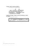
Page 82: ...A warning statement View the Chinese Class A warning statement Japanese Voluntary Control Council for Interference VCCI statement View the Japanese VCCI statement 70 JS23 JS43 Type 7778 Installation and User s Guide ...

Page 83: ...7 I O expansion card 17 input output 46 memory 17 microprocessor 17 serial attached SCSI SAS 17 system board 17 control panel buttons and LEDs 13 controller enumeration 52 Ethernet 51 memory 9 cover closing 43 installing 43 opening 26 removing 26 creating CE login 51 D danger statements 5 data integrity 9 daughter card see expansion card 37 diagnostic CD for AIX operating system 59 diagnostic tool...

Page 84: ...ment 56 Web site for other programs for remote deployment 56 location code 59 logical HEA MAC addresses 53 M MAC addressing scheme 53 meanings of colors on components 23 memory module installation order 34 installing 34 removing 33 specifications 6 9 supported 7 memory RDIMM planning 36 memory specifications 6 microprocessor specifications 6 Myrinet card I O expansion 37 N network operating system...

Page 85: ...ility 50 system reliability 24 system board connectors 17 systems management 11 T telephone numbers 63 TEMP image starting 49 trademarks 66 troubleshooting diagnostic utilities programs for Linux operating system 59 Light path diagnostics 59 Problem isolation tables 59 Web site and diagnostic CD for AIX operating system 59 turning off the blade server 16 turning on the blade server 16 U UK telecom...

Page 86: ...74 JS23 JS43 Type 7778 Installation and User s Guide ...

Page 87: ......

Page 88: ... Part Number 44R5338 Printed in USA 1P P N 44R5338 ...

Reviews: