background image

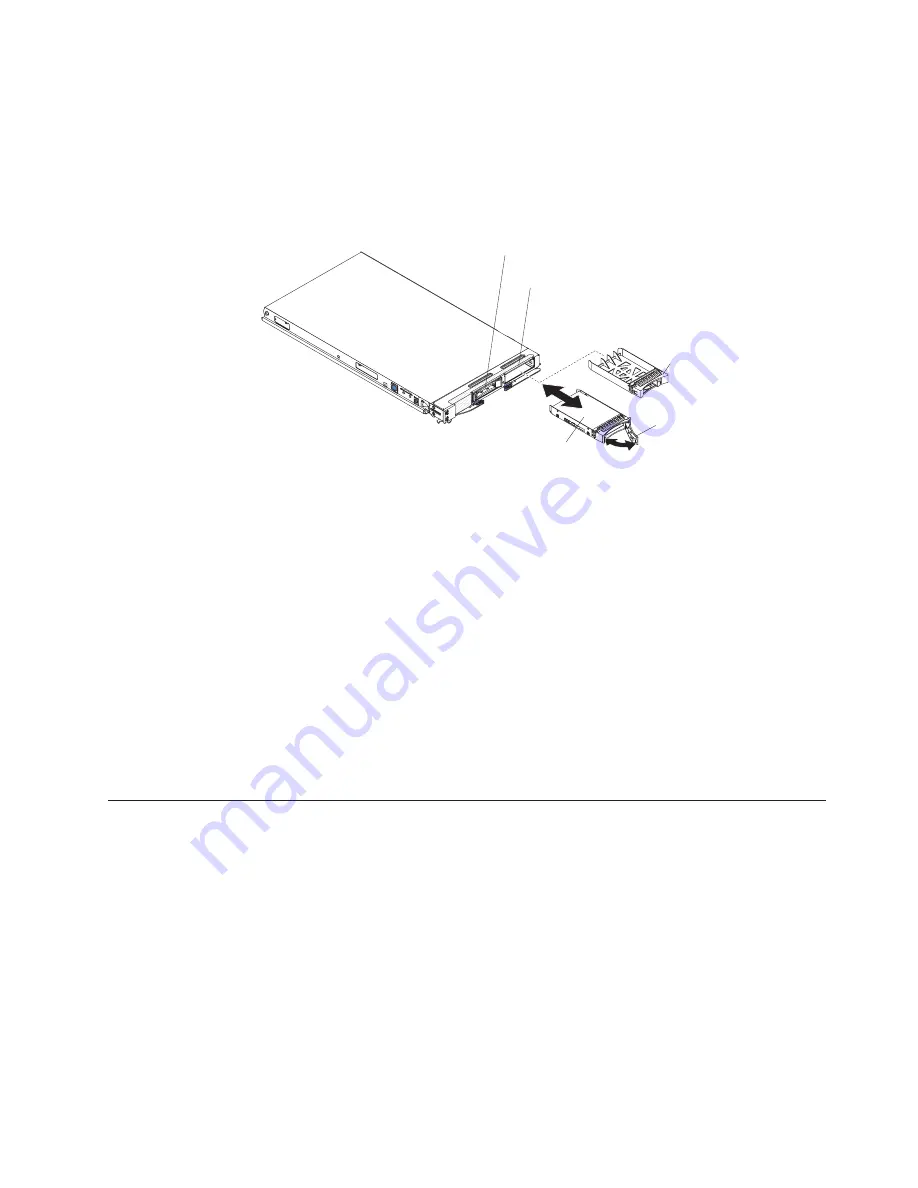
installed in the blade server in storage bay 0. If the blade server is equipped with
one storage drive, you can install an additional drive in storage bay 1. These two
SAS hard disk drives support RAID 0 and RAID 1 (use to implement and manage
a redundant array of independent disks (RAID) level-1 array). See “Configuring a
SAS RAID array” on page 42 for information about SAS RAID configuration.

To install a hot-swap hard disk drive, complete the following steps.

Hot-swap
storage drive

Storage
drive filler

Storage drive
release handle

Hot-swap storage bay 1

Hot-swap storage bay 0

1.

Before you begin, read “Safety” on page v and “Installation guidelines” on
page 15.

2.

Identify the blade server storage bay (hot-swap storage bay 0 or hot-swap
storage bay 1) in which the hard disk drive will be installed.

3.

If a storage-bay filler is installed, remove it from the blade server by lifting the
release levers and pulling it away from the blade server.

4.

Touch the static-protective package that contains the hard disk drive to any

unpainted

metal surface on the BladeCenter unit or any

unpainted

metal surface

on any other grounded rack component; then, remove the hard disk drive from
the package.

5.

Open the release lever on the hot-swap hard disk drive and slide the drive into
the storage bay until it is firmly seated in the connector.

6.

Lock the hard disk drive into place by closing the release lever.

If you have other devices to install or remove, do so now; otherwise, go to
“Completing the installation” on page 30.

Installing a memory module

Use these instructions to install memory modules in the blade server.

The following notes describe the types of direct inline memory modules (DIMMs)
that the blade server supports and other information that you must consider when
you install DIMMs:

Note:

1.

The following illustration shows the location of the DIMM connectors on the
system board.

2.

The illustrations in this document might differ slightly from your hardware.

v

The system board has DIMM connectors.

v

The server supports two-way memory interleaving.

Chapter 3. Installing options

21

Summary of Contents for BladeCenter HS12 Type 8014

Page 1: ...er on the IBM support Web site Before you install the BladeCenter HS12 Type 8014 or 8028 blade server in a BladeCenter unit complete the following procedures Install and configure the rack according t...

Page 2: ...ify that all optional devices you installed are on the ServerProven list at http www ibm com servers eserver serverproven compat us Is the server working correctly Is the problem solved Hardware or so...

Page 3: ...BladeCenter HS12 Type 8014 or 8028 Installation and User s Guide...

Page 4: ...es on page 55 and the Warranty and Support Information document for your blade server type on the IBM Documentation CD Sixth edition May 2010 Copyright IBM Corporation 2008 2010 US Government Users Re...

Page 5: ...e Setup and Installation CD 39 ServerGuide features 39 Setup and configuration overview 39 Typical operating system installation 40 Installing the operating system without using ServerGuide 40 Using t...

Page 6: ...iv BladeCenter HS12 Type 8014 or 8028 Installation and User s Guide...

Page 7: ...fterne f r du installerer dette produkt Lees voordat u dit product installeert eerst de veiligheidsvoorschriften Ennen kuin asennat t m n tuotteen lue turvaohjeet kohdasta Safety Information Avant d i...

Page 8: ...led with a number This number is used to cross reference an English language caution or danger statement with translated versions of the caution or danger statement in the Safety Information document...

Page 9: ...and disconnect cables as described in the following table when installing moving or opening covers on this product or attached devices To Connect To Disconnect 1 Turn everything OFF 2 First attach al...

Page 10: ...r source Always replace the blade cover before installing the blade United Kingdom telecommunications safety requirement Notice to Customers This apparatus is approved under approval number NS G 1234...

Page 11: ...are software CDs that help you to configure hardware install device drivers and install the operating system To download the latest device drivers complete the following steps Note Changes are made p...

Page 12: ...ou register the blade server with IBM You can register the blade server at http www ibm com support mysupport Product name BladeCenter HS12 Machine type _____________________________________________ M...

Page 13: ...te the corresponding statement in your language in the Safety Information document v Warranty and Support Information This document is in PDF on the IBM Documentation CD It contains information about...

Page 14: ...rt the CD into the CD or DVD drive and click Start Run In the Open field type e win32 bat where e is the drive letter of the CD or DVD drive and click OK If you are using Red Hat Linux insert the CD i...

Page 15: ...ents indicate situations that can be potentially hazardous to you A caution statement is placed just before the description of a potentially hazardous procedure step or situation v Danger These statem...

Page 16: ...h the cKVM and removable media drives v Serial over LAN SOL v Redundant buses for communication with keyboard mouse and removable media drives Environment v Air temperature Blade server on 10 C to 35...

Page 17: ...etup and Installation CD see Using the ServerGuide Setup and Installation CD on page 39 v Microprocessor technology The blade server supports an Intel LGA 771 microprocessor Depending on the model the...

Page 18: ...rver when you need it and the ease with which you can diagnose and correct problems Three of the most important features in server design are reliability availability and serviceability RAS These RAS...

Page 19: ...ng systems that support IBM Director see the IBM Director Compatibility Document This document is in Portable Document Format PDF at http www ibm com systems management director resources It is update...

Page 20: ...Field Replaceable Units FRUs Customer Replaceable Units CRUs and optional devices The following illustration shows the major components of the blade server PR ES S HE RE W HE N IN ST AL LI NG CA RD Mi...

Page 21: ...request is being processed and then is lit when the ownership of the keyboard video and mouse has been transferred to the blade server It can take approximately 20 seconds to switch the keyboard video...

Page 22: ...rver has been placed in the management module event log The information LED can be turned off through the management module Web interface at or through IBM Director Console For more information about...

Page 23: ...es not respond 2 While the blade server is starting the power on LED on the front of the blade server is lit See Blade server controls and LEDs on page 11 for the power on LED states v If a power fail...

Page 24: ...n see the IBM BladeCenter Management Module User s Guide or go to http www 03 ibm com systems management for more information Blade server connectors Use this information to locate blade server system...

Page 25: ...x of downloadable files for the blade server v Observe good housekeeping in the area where you are working Place removed covers and other parts in a safe place v Back up all important data before you...

Page 26: ...ld up around you v Handle the device carefully holding it by its edges or its frame v Do not touch solder joints pins or exposed circuitry v Do not leave the device where others can handle and damage...

Page 27: ...ng system then press the power control button behind the blade server control panel door to turn off the blade server see Turning off the blade server on page 13 for more information Attention Wait at...

Page 28: ...server or expansion unit and lift the cover open as shown in the illustration 6 Lay the cover flat or lift it from the blade server and store for future use Statement 21 CAUTION Hazardous energy is p...

Page 29: ...ws or levers c Rotate the expansion unit open then lift the expansion unit from the blade server 6 If you are instructed to return the cover or an optional expansion unit follow all packaging instruct...

Page 30: ...e connector until the drive moves past the storage drive release lever and is firmly seated in the connector Attention Do not press on the top of the drive Pressing on the top might damage the drive 8...

Page 31: ...4 Touch the static protective package that contains the hard disk drive to any unpainted metal surface on the BladeCenter unit or any unpainted metal surface on any other grounded rack component then...

Page 32: ...0 Dual rank Dual rank Single rank v All DIMMs in a pair or group must be the same size speed type technology and physical design You can use compatible DIMMs from different manufacturers v Install onl...

Page 33: ...nted metal surface on any other grounded rack component in the rack in which you are installing the DIMM for at least 2 seconds then remove the DIMM from its package 9 To install the DIMMs repeat the...

Page 34: ...e blade server To install a cKVM card complete the following steps Notes 1 The following illustration shows the location and how to install a cKVM card in the system board 2 The illustrations in this...

Page 35: ...ling the card in an expansion unit is similar The blade server supports various types of I O expansion cards See http www ibm com servers eserver serverproven compat us for a list of available I O exp...

Page 36: ...alled the specific location of connectors and other components might be different from the illustrations in this document or your BladeCenter documentation Make sure that the BladeCenter unit and the...

Page 37: ...y unpainted metal surface on any other grounded rack component for at least 2 seconds 8 Remove the I O expansion card from its static protective package 9 Locate the three I O expansion card connector...

Page 38: ...page 30 Installing a high speed expansion card Use these instructions to install a high speed expansion card in the blade server To install a high speed expansion card complete the following steps Not...

Page 39: ...install or remove do so now otherwise go to Completing the installation on page 30 Installing an optional expansion unit Use these instructions to install an optional expansion unit The optional expan...

Page 40: ...ith and connect to the connectors in the system board If you have other expansion units to install do so now otherwise go to Completing the installation Completing the installation To complete the ins...

Page 41: ...the rear of the blade server as shown in the illustration Before you close the cover make sure that all components are installed and seated correctly and that you have not left loose tools or parts i...

Page 42: ...er unit b To help ensure proper cooling performance and system reliability make sure that each I O module bay on the front of the BladeCenter unit contains a blade server expansion unit or blade fille...

Page 43: ...tility program automatically starts so that you can save the new configuration settings See Using the Configuration Setup Utility program on page 35 for more information about the Configuration Setup...

Page 44: ...34 BladeCenter HS12 Type 8014 or 8028 Installation and User s Guide...

Page 45: ...g this CD see Using the ServerGuide Setup and Installation CD on page 39 v Preboot Execution Environment PXE boot agent utility program The PXE boot agent utility program is part of the BIOS Use it to...

Page 46: ...information about the USB devices in the blade server v System Information Select this menu item to view information about the blade server When you make configuration changes through other options in...

Page 47: ...hecks for changes in the boot record when the blade server starts v Advanced Setup Select this menu item to change settings for advanced hardware features Important The blade server might malfunction...

Page 48: ...ncel the changes that you have made in the settings and restore the previous settings v Load Default Settings Select this menu item to cancel the changes that you have made in the settings and restore...

Page 49: ...programs that are based on detected hardware v Device drivers that are provided for the blade server model and detected hardware v Operating system partition size and file system type that are selecta...

Page 50: ...ocess the operating system installation program starts You will need the operating system CD to complete the installation 2 The ServerGuide program stores information about the blade server model serv...

Page 51: ...onds by default to press Ctrl S after the prompt is displayed If the PXE setup prompt is not displayed use the Configuration Setup Utility program to set the Enable Ethernet PXE DHCP option 3 Use the...

Page 52: ...inks click Publications lookup 4 From the Product family menu select BladeCenter HS12 and click Continue Configuring a SAS RAID array Use this information to configure a SAS RAID array Configuring a S...

Page 53: ...following tasks v Set the SAS device scan order v Set the SAS ID for the controller v Manage the SAS RAID configuration To start the LSI Logic Configuration Utility program complete the following step...

Page 54: ...44 BladeCenter HS12 Type 8014 or 8028 Installation and User s Guide...

Page 55: ...Setup and Installation CD to install the blade server operating system To use the ServerGuide Setup and Installation CD complete the following steps 1 While the blade server is on press the KVM selec...

Page 56: ...the IBM Web site The actual procedure might vary slightly from what is described in this document 1 Go to http www ibm com systems support 2 Under Product support click BladeCenter 3 From the menu on...

Page 57: ...n CD Diagnostic tools overview Use this overview to locate specific diagnostic tools to diagnose and solve hardware related problems The following tools are available to help you diagnose and solve ha...

Page 58: ...rmation about the blade server System configuration Network interfaces and settings Installed hardware Light path diagnostics status Vital product data firmware and BIOS configuration Storage drive he...

Page 59: ...request IRQ assignments See Configuring a SAS RAID array on page 42 v Make sure that the storage drive is connected correctly See Blade server connectors on page 14 to locate the storage drive connec...

Page 60: ...50 BladeCenter HS12 Type 8014 or 8028 Installation and User s Guide...

Page 61: ...ware and firmware if the problem has a documented solution within a software upgrade You can obtain the latest downloads for your system from http www ibm com systems support supportsite wss docdispla...

Page 62: ...and updates To access these pages go to http www ibm com systems support You can find the most up to date product information for the IBM BladeCenter HS12 Type 8014 8028 and 1916 in http publib bould...

Page 63: ...m com planetwide In the U S and Canada call 1 800 IBM SERV 1 800 426 7378 In the U S and Canada hardware service and support is available 24 hours a day 7 days a week In the U K these services are ava...

Page 64: ...54 BladeCenter HS12 Type 8014 or 8028 Installation and User s Guide...

Page 65: ...ARTICULAR PURPOSE Some states do not allow disclaimer of express or implied warranties in certain transactions therefore this statement may not apply to you This information could include technical in...

Page 66: ...ers Important notes Processor speed indicates the internal clock speed of the microprocessor other factors also affect application performance CD or DVD drive speed is the variable read rate Actual sp...

Page 67: ...the levels of particulates or gases in your environment have caused damage to the device IBM may condition provision of repair or replacement of devices or parts on implementation of appropriate remed...

Page 68: ...s and can radiate radio frequency energy and if not installed and used in accordance with the instruction manual may cause harmful interference to radio communications Operation of this equipment in a...

Page 69: ...artment M456 IBM Allee 1 71137 Ehningen Germany Telephone 49 7032 15 2937 Email tjahn de ibm com Germany Class A statement Deutschsprachiger EU Hinweis Hinweis f r Ger te der Klasse A EU Richtlinie zu...

Page 70: ...dem Deutschen EMVG das EG Konformit tszeichen CE zu f hren Verantwortlich f r die Einhaltung der EMV Vorschriften ist der Hersteller International Business Machines Corp New Orchard Road Armonk New Yo...

Page 71: ...a Communications Commission KCC statement Please note that this equipment has obtained EMC registration for commercial use In the event that it has been mistakenly sold or purchased please exchange it...

Page 72: ...62 BladeCenter HS12 Type 8014 or 8028 Installation and User s Guide...

Page 73: ...tronic emission notices 58 error log 47 Ethernet controller 6 configuring 42 European Union EMC Directive conformance statement 59 event log 47 exit configuration utility 36 expansion card installing...

Page 74: ...A electronic emission statement 60 port input output 33 power throttling 6 power on password 38 Preboot eXecution Environment PXE option 36 disabling 36 enabling 36 problems hardware 47 problems solv...

Page 75: ...board components location of 10 system board connectors 14 systems management 9 T Taiwan Class A compliance statement 60 trademarks 56 troubleshooting Light path diagnostics 47 Problem isolation table...

Page 76: ...66 BladeCenter HS12 Type 8014 or 8028 Installation and User s Guide...

Page 77: ......

Page 78: ...Part Number 60Y1600 Printed in USA 1P P N 60Y1600...

Reviews: