background image

Major


components


of


the


blade


workstation


You


must


remove


the


blade


workstation


from


the


BladeCenter


unit


and


remove


the


cover


to


see


the


components.


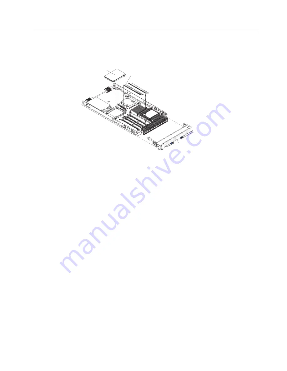
The


following


illustration


shows


the


major


components


of


a


BladeCenter


HC10


Type


7996


blade


workstation.


Bezel

SATA storage
drive

DIMMs


Chapter


1.


Introduction


9

Summary of Contents for BladeCenter HC10 Type 7996

Page 1: ...ation on the IBM Support Web site Before installing the BladeCenter HC10 Type 7996 blade workstation in a BladeCenter unit complete the following procedures Install and configure the rack according to the documentation that came with the rack Install the BladeCenter unit into the rack and configure it according to the documentation provided with the BladeCenter unit Supply 200 240 V ac to the Blad...

Page 2: ...rify that all optional devices you installed are on the ServerProven list at http www ibm com servers eserver serverproven compat us Is the blade workstation working correctly Is the problem solved Hardware or software problem View support telephone numbers at http www ibm com planetwide View information about IBM Support Line at or view support telephone numbers at http www ibm com services sl pr...

Page 3: ...BladeCenter HC10 Type 7996 Installation and User s Guide ...

Page 4: ...ty and Support Information document on the IBM BladeCenter Documentation CD that comes with your BladeCenter device First Edition July 2007 Copyright International Business Machines Corporation 2007 All rights reserved US Government Users Restricted Rights Use duplication or disclosure restricted by GSA ADP Schedule Contract with IBM Corp ...

Page 5: ...stalling a SATA storage drive 19 Removing a SATA storage drive 19 Installing memory modules 20 Completing the installation 22 Installing the blade workstation bezel assembly 22 Closing the blade workstation cover 23 Installing the blade workstation in a BladeCenter unit 24 Updating the blade workstation configuration 25 Input output connectors and devices 26 Chapter 4 Configuring the blade worksta...

Page 6: ...lems 45 Appendix A Getting help and technical assistance 47 Before you call 47 Using the documentation 47 Getting help and information from the World Wide Web 47 Software service and support 48 Hardware service and support 48 IBM Taiwan product service 48 Appendix B Notices 49 Trademarks 49 Important notes 50 Product recycling and disposal 51 Battery return program 52 Electronic emission notices 5...

Page 7: ...än tuotteen lue turvaohjeet kohdasta Safety Information Avant d installer ce produit lisez les consignes de sécurité Vor der Installation dieses Produkts die Sicherheitshinweise lesen Prima di installare questo prodotto leggere le Informazioni sulla Sicurezza Les sikkerhetsinformasjonen Safety Information før du installerer dette produktet Antes de instalar este produto leia as Informações sobre S...

Page 8: ...tion document For example if a caution statement is labeled Statement 1 translations for that caution statement are in the Safety Information document under Statement 1 Be sure to read all caution and danger statements in this document before you perform the procedures Read any additional safety information that comes with the blade workstation or optional device before you install the device vi B...

Page 9: ...equipment when there is evidence of fire water or structural damage v Disconnect the attached power cords telecommunications systems networks and modems before you open the device covers unless instructed otherwise in the installation and configuration procedures v Connect and disconnect cables as described in the following table when installing moving or opening covers on this product or attached...

Page 10: ...ent 3 CAUTION When laser products such as CD ROMs DVD drives fiber optic devices or transmitters are installed note the following v Do not remove the covers Removing the covers of the laser product could result in exposure to hazardous laser radiation There are no serviceable parts inside the device v Use of controls or adjustments or performance of procedures other than those specified herein mig...

Page 11: ... from the device ensure that all power cords are disconnected from the power source 1 2 Statement 8 CAUTION Never remove the cover on a power supply or any part that has the following label attached Hazardous voltage current and energy levels are present inside any component that has this label attached There are no serviceable parts inside these components If you suspect a problem with one of the...

Page 12: ... on top of rack mounted devices Statement 21 CAUTION Hazardous energy is present when the blade is connected to the power source Always replace the blade cover before installing the blade x BladeCenter HC10 Type 7996 Installation and User s Guide ...

Page 13: ...ers 4 Click BladeCenter HC10 to display the matrix of downloadable files for the BladeCenter product The blade workstation comes with a limited warranty For information about the terms of the warranty and getting service and assistance see the Warranty and Support Information document for your blade workstation on the IBM BladeCenter Documentation CD You can obtain up to date information about the...

Page 14: ...mber _____________________________________________ Note The model number and serial number are on the ID label that is behind the control panel door on the front of the blade workstation and on a label on the side of the blade workstation that is visible when the blade workstation is not in the BladeCenter unit The following illustration shows the HC10 blade workstation Note The illustrations in t...

Page 15: ...ocumentation This Installation and User s Guide contains general information about the blade workstation including how to install supported optional devices and how to configure the blade workstation The following documentation also comes with the blade workstation v Problem Determination and Service Guide This document is in PDF on the IBM BladeCenter Documentation CD It contains information to h...

Page 16: ...t Format PDF and includes the IBM Documentation Browser to help you find information quickly Hardware and software requirements You can run the IBM BladeCenter Documentation CD on any system that meets the hardware and software requirements The IBM BladeCenter Documentation CD requires the following minimum hardware and software v Microsoft Windows XP Windows 2000 or Red Hat Linux v 100 MHz microp...

Page 17: ...ent to view it and press Crtl F to use the Acrobat search function or press Alt F to use the xpdf search function within the document Click Help for detailed information about using the Documentation Browser Notices and statements in this document The caution and danger statements in this document are also in the multilingual Safety Information document which is on the IBM BladeCenter Documentatio...

Page 18: ...n SATA IO storage drive v 60 GB or larger v 5400 rpm if hard disk drive or faster Integrated functions v Q965 Express chip set with ICH8 v Broadcom Gigabit Ethernet controller with TCP IP offload engine TOE v Local service processor Baseboard management controller BMC with Intelligent Platform Management Interface IPMI firmware and Serial over LAN SOL v Local service processor BMC v RS 485 interfa...

Page 19: ...network to the communication module of the thin client The user interface has the same function and appearance as a workstation at the user location would provide v High speed high resolution 2D or 3D graphics capability Depending on the graphics controller that is installed the blade workstation supports either 2D or 3D high resolution graphics when it communicates with the thin client The Graphi...

Page 20: ...ion and Power Interface ACPI v Automatic error retry or recovery v Automatic restart v Built in monitoring for temperature and voltage v Upgradeable basic input output system BIOS code v Support center 24 hours per day 7 days a week1 v Diagnostic support of the Ethernet controller v Error codes and messages v Power on self test POST v Processor serial number access v ROM resident diagnostics v Ser...

Page 21: ...move the blade workstation from the BladeCenter unit and remove the cover to see the components The following illustration shows the major components of a BladeCenter HC10 Type 7996 blade workstation Bezel SATA storage drive DIMMs Chapter 1 Introduction 9 ...

Page 22: ...10 BladeCenter HC10 Type 7996 Installation and User s Guide ...

Page 23: ...ough the management module to do so v You can turn on the blade workstation remotely by using the management module v If the blade workstation is connected to power the power on LED is flashing slowly the operating system supports the Wake on LAN feature and the Wake on LAN feature has not been disabled through the management module the Wake on LAN feature can turn on the blade workstation v The t...

Page 24: ...hip of the keyboard video and mouse has been transferred to the blade workstation It can take approximately 20 seconds to switch the keyboard video and mouse control from one blade workstation to another Using a keyboard that is directly attached to the management module you can also press keyboard keys in the following sequence to switch KVM control between blade workstations NumLock NumLock bay_...

Page 25: ...ed off through the management module Web interface or through IBM Director Console Information LED When this amber LED is lit it indicates that information about a system error for the blade workstation has been placed in the system error log The information LED can be turned off through the management module Web interface or through IBM Director Console Blade error LED When this amber LED is lit ...

Page 26: ...ve Video controller Compression card System board switches and jumpers The following illustration shows the location of the clear CMOS button and the jumper that is used to recover BIOS See the information about how and when to use the switches jumpers or buttons in the Problem Determination and Service Guide on the IBM BladeCenter Documentation CD BIOS recovery jumper Clear CMOS button 14 BladeCe...

Page 27: ...onent for any additional procedures that you might have to perform before you remove or install the component v For a list of supported optional devices for the blade workstation go to http www ibm com servers eserver serverproven compat us System reliability guidelines To help ensure proper cooling and system reliability do not operate the BladeCenter unit without a blade device or filler blade i...

Page 28: ... blade workstation note the bay number Reinstalling a blade workstation into a different bay than the one it was removed from can have unintended consequences Some configuration information and update options are established according to bay number if you reinstall the blade workstation into a different bay you might have to reconfigure the blade workstation To remove the blade workstation complet...

Page 29: ... see Removing the blade workstation from the BladeCenter unit on page 16 for instructions 3 Carefully lay the blade workstation on a flat static protective surface with the cover side up 4 Press the blade cover release on each side of the blade workstation and lift the cover open as shown in the illustration 5 Lay the cover flat or lift it from the blade workstation and store it for future use Sta...

Page 30: ...following steps 1 Read the safety information that begins on page v and Installation guidelines on page 15 2 Open the blade workstation cover see Opening the blade workstation cover on page 17 for instructions 3 Disconnect the control panel cable from the control panel connector 4 Press the bezel assembly release and pull the bezel assembly away from the blade workstation approximately 1 2 cm 0 5 ...

Page 31: ... page 16 for instructions 3 Carefully lay the blade workstation on a flat static protective surface 4 Open the blade workstation cover see Opening the blade workstation cover on page 17 for instructions 5 Locate the SATA connector Attention Do not press on the top of the drive Pressing the top might damage the drive 6 Orient the drive so that the connector on the drive aligns with the SATA connect...

Page 32: ...Both DIMMs in a pair must be of the same size speed type technology and physical design You can mix compatible DIMMs from different manufacturers v The second pair of DIMMs does not have to be of the same size speed type technology and physical design as the first pair v Install only 1 8 V 240 pin DDR2 PC2 5300 SDRAM with non ECC DIMMs that are compatible with the latest PC2 5300 SDRAM DIMM specif...

Page 33: ...from its package 8 Complete the following steps for each DIMM that you install a Open the retaining clips on the DIMM connector b Turn the DIMM so that the DIMM keys align correctly with the connector on the system board Attention To avoid breaking the retaining clips or damaging the DIMM connectors handle the clips gently c Insert the DIMM by pressing the DIMM along the guides into the connector ...

Page 34: ...ertain optional devices run the blade workstation Configuration Setup Utility program see Updating the blade workstation configuration on page 25 Note If you have just connected the power cords of the BladeCenter unit to electrical outlets you must wait until the power on LED on the blade workstation flashes slowly before you press the power control button Installing the blade workstation bezel as...

Page 35: ... 2 If you removed the blade bezel assembly replace it now see Installing the blade workstation bezel assembly on page 22 for instructions 3 Make sure that all components are installed and seated correctly and that you have not left loose tools or parts inside the blade workstation 4 Make sure that the control panel cable and all other cables are placed so that the cover does not crimp or pinch the...

Page 36: ...n a BladeCenter T unit power modules must be present in all four power module bays b To help ensure proper cooling performance and system reliability make sure that each of the blade bays on the front of the BladeCenter unit has a blade workstation or filler blade installed Do not operate a BladeCenter unit for more than 1 minute or a BladeCenter T unit for more than 20 minutes without a blade wor...

Page 37: ... filter must then be provided on the rack If you reinstall a blade device that you removed you must install it in the same blade bay from which you removed it Some blade device configuration information and update options are established according to bay number Reinstalling a blade device into a different blade bay from the one from which it was removed might have unintended consequences and you m...

Page 38: ... information about these buttons and their functions The Ethernet controller in the blade workstation communicates with the network through an Ethernet compatible I O module the default is I O module 1 on the BladeCenter unit Network signals to and from the blade workstation are automatically routed to the I O module through circuitry in the blade workstation and the BladeCenter unit The compressi...

Page 39: ...le and disable the Broadcom NetXtreme II Ethernet Boot Agent from the Configuration Setup Utility program For information see Enabling the Broadcom NetXtreme II Ethernet Boot Agent on page 35 For information about configuring the integrated Ethernet controller see Configuring the Broadcom NetXtreme Gigabit Ethernet controller on page 35 For information about setting up the network configuration fo...

Page 40: ...with a connection manager or connection broker for connection to the thin client For a description of the registration process see the documentation that comes with the connection broker software that you purchased Note The compression card DNS Discovery Prefix factory setting is ws broker If DHCP is not enabled you can change the compression card static IP address in either of two ways v Using th...

Page 41: ...field then press Enter 4 In the resulting window click Configuration Network 5 Change the IP address subnet mask and gateway address of the compression card 6 Click Apply 7 Close the Web browser 8 Turn off the blade workstation then turn it on again 9 Determine the MAC address of the compression card you will need the compression card IP address and MAC address when you establish a session from a ...

Page 42: ...h Dynamic Host Configuration Protocol DHCP the connection broker automatically establishes a session between the thin client and the target blade workstation See the documentation that comes with the connection broker software for instructions and information about session establishment If you are not using the Connection Broker software you must explicitly establish the session yourself To explic...

Page 43: ... steps 1 Turn on the blade workstation see Turning on the blade workstation on page 11 2 Immediately give the blade workstation control of the BladeCenter unit shared keyboard video and mouse ports v If you are managing the blade workstation by using the BladeCenter system console press the KVM select button on the blade workstation see The control panel buttons and LEDs on page 12 for information...

Page 44: ...rial remote video and keyboard redirection System MAC Addresses Select this choice to view the MAC addresses for network devices that are installed in the blade workstation Note This choice is available only if at least one Preboot Execution Environment PXE option read only memory ROM starts during POST Video Select this choice to view information about the video controller and memory v Date and T...

Page 45: ...y This choice is on the full Configuration Setup Utility menu only CPU Options Select this choice to view or change the microprocessor options PCI Bus Control Select this choice to view or change the system resources that are used by the installed PCI or PCI Express devices Baseboard Management Controller BMC Settings Select this choice to view the baseboard management controller BMC information a...

Page 46: ... menu You can use any combination of up to seven characters A Z a z and 0 9 for the password Keep a record of your password in a secure place If you forget the power on password you can regain access to the blade workstation in any of the following ways v Remove the blade workstation battery and then reinstall it see the Problem Determination and Service Guide on the IBM BladeCenter Documentation ...

Page 47: ...etXtreme II Ethernet Boot Agent To use the Broadcom NetXtreme II Ethernet Boot Agent program complete the following steps 1 Turn off the blade workstation 2 Restart the blade workstation 3 At the prompt for the NetXtreme II Ethernet Boot Agent program press Ctrl S Configuring the Broadcom NetXtreme Gigabit Ethernet controller The Ethernet controller is integrated on the system board It provides an...

Page 48: ... the firmware versions that are available Click Monitors Firmware VPD in the Advanced Management Module user interface to check the firmware levels in the blade workstation If the date and revision level on the Web site is later than the date and revision level in the blade workstation download and install the firmware from the Web To locate the blade workstation firmware updates complete the foll...

Page 49: ...ate the firmware on the compression card that is in the blade workstation use the connection broker software or see Updating the compression card firmware on page 30 To update the management module firmware by using the management module Web based user interface complete the following steps 1 Start the management module management and configuration program For more information see the Management M...

Page 50: ...ion operating system has for the controller 4 Ping an external computer on the network that the switch module or pass thru module is connected to If you can ping the external computer the Ethernet controller is associated with the switch module or pass thru module in I O module bay 1 Communication from the user interface compression card is routed to the Ethernet capable switch module or pass thru...

Page 51: ...station to enable SOL operation The blade workstation supports SOL sessions on VLAN 4095 only make sure to configure the SOL function to operate on VLAN 4095 Hardware requirements For the HC10 Type 7996 blade workstation SOL uses the Ethernet 1 network interface Planar Ethernet and an Ethernet I O module in the BladeCenter unit I O bay 1 to communicate Software requirements Make sure that you are ...

Page 52: ...e SOL function to operate on VLAN 4095 Configuring the blade workstation BIOS for SOL To configure the blade workstation BIOS to enable SOL complete the following steps Note The BladeCenter HC10 blade workstation supports the SOL connection on serial port A only 1 Update the blade workstation BIOS a Download the latest version of BIOS code for the blade workstation from http www ibm com systems su...

Page 53: ...n end an SOL session monitor an SOL session and restart a blade workstation through SOL The following table contains the escape key sequences to use during a blade workstation SOL session when using the VT100 terminal emulation mode the default Note There is a time limit for entering an escape key sequence If an escape key sequence does not appear to work it might be because the time limit for ent...

Page 54: ...c 8 F9 Esc 9 F10 Esc 0 F11 Esc F12 Esc Home Esc h Insert Esc Left arrow Esc D Page Down Esc Page Up Esc Print Screen Esc i Right arrow Esc C Shift Print Screen Esc 2 i Shift Tab Esc Z Up arrow Esc A 42 BladeCenter HC10 Type 7996 Installation and User s Guide ...

Page 55: ...the blade workstation to recognize and use the removable media drives and front panel USB ports Downloading installation instructions To download operating system installation instructions complete the following steps Note Changes are made periodically to the IBM Web site The actual procedure might vary slightly from what is described in this document 1 Go to http www ibm com systems support 2 Und...

Page 56: ...44 BladeCenter HC10 Type 7996 Installation and User s Guide ...

Page 57: ...roblem Determination and Service Guide for your blade workstation on the IBM BladeCenter Documentation CD The following tools are available to help you diagnose and solve hardware related problems v POST beep codes The power on self test beep codes indicate the detection of a problem One beep indicates successful completion of POST More than one beep indicates a problem Beep codes are listed in Di...

Page 58: ...46 BladeCenter HC10 Type 7996 Installation and User s Guide ...

Page 59: ...iagnostic tests that you can perform Most systems operating systems and programs come with documentation that contains troubleshooting procedures and explanations of error messages and error codes If you suspect a software problem see the documentation for the operating system or program Using the documentation Information about your IBM system and preinstalled software if any or optional device i...

Page 60: ...ibm com planetwide for support telephone numbers In the U S and Canada call 1 800 IBM SERV 1 800 426 7378 Hardware service and support You can receive hardware service through IBM Services or through your IBM reseller if your reseller is authorized by IBM to provide warranty service See http www ibm com planetwide for support telephone numbers or in the U S and Canada call 1 800 IBM SERV 1 800 426...

Page 61: ...NCLUDING BUT NOT LIMITED TO THE IMPLIED WARRANTIES OF NON INFRINGEMENT MERCHANTABILITY OR FITNESS FOR A PARTICULAR PURPOSE Some states do not allow disclaimer of express or implied warranties in certain transactions therefore this statement may not apply to you This information could include technical inaccuracies or typographical errors Changes are periodically made to the information herein thes...

Page 62: ...ates other countries or both Linux is a registered trademark of Linus Torvalds in the United States other countries or both Red Hat the Red Hat Shadow Man logo and all Red Hat based trademarks and logos are trademarks or registered trademarks of Red Hat Inc in the United States and other countries Other company product or service names may be trademarks or service marks of others Important notes P...

Page 63: ...rn programs and services in several countries to assist equipment owners in recycling their IT products Information on IBM product recycling offerings can be found on IBM s Internet site at http www ibm com ibm environment products prp shtml Esta unidad debe reciclarse o desecharse de acuerdo con lo establecido en la normativa nacional o local aplicable IBM recomienda a los propietarios de equipos...

Page 64: ...y potential effects of EEE on the environment and human health due to the potential presence of hazardous substances in EEE For proper collection and treatment contact your local IBM representative Battery return program This product may contain a sealed lead acid nickel cadmium nickel metal hydride lithium or lithium ion battery Consult your user manual or service manual for specific battery info...

Page 65: ...e vie selon cette norme In accordance with the European Directive 2006 66 EC batteries and accumulators are labeled to indicate that they are to be collected separately and recycled at end of life The label on the battery may also include a chemical symbol for the metal concerned in the battery Pb for lead Hg for mercury and Cd for cadmium Users of batteries and accumulators must not dispose of ba...

Page 66: ...ference and 2 this device must accept any interference received including interference that may cause undesired operation Industry Canada Class A emission compliance statement This Class A digital apparatus complies with Canadian ICES 003 Avis de conformité à la réglementation d Industrie Canada Cet appareil numérique de la classe A est conforme à la norme NMB 003 du Canada Australia and New Zeala...

Page 67: ...ronment this product may cause radio interference in which case the user may be required to take adequate measures European Community contact IBM Technical Regulations Pascalstr 100 Stuttgart Germany 70569 Telephone 0049 0 711 785 1176 Fax 0049 0 711 785 1283 E mail tjahn de ibm com Taiwanese Class A warning statement Chinese Class A warning statement Japanese Voluntary Control Council for Interfe...

Page 68: ...56 BladeCenter HC10 Type 7996 Installation and User s Guide ...

Page 69: ...iguring the blade workstation 27 the Ethernet controller 35 connectors battery 14 input output 26 memory 14 microprocessor 14 SATA 14 system board 14 controller Ethernet 35 memory 7 cover closing 23 opening 17 D data rate Ethernet controller 35 diagnostic tools 45 DIMM See memory module documentation CD 4 documentation CD requirements hardware 4 software 4 drive internal install 19 support 7 E ele...

Page 70: ...tation cover 17 operating system installing 43 supported 43 optional devices installing 15 order of installation memory modules 20 P password power on 34 setting 32 PCI configuration 33 placement of labels 3 port input output 26 power on password 34 problems hardware 45 solving 45 processor control 33 product data 1 product recycling and disposal 51 PXE boot agent utility program using 36 R recycl...

Page 71: ...on the blade workstation 11 U United States electronic emission Class A notice 54 United States FCC Class A notice 54 updating firmware 36 using Boot Menu program 34 jumpers 14 passwords 32 switches 14 utility Configuration Setup Utility program 27 PXE boot agent program using 36 W web site publication ordering 47 support 47 support line telephone numbers 48 Web site supported blade workstation op...

Page 72: ...60 BladeCenter HC10 Type 7996 Installation and User s Guide ...

Page 73: ......

Page 74: ... Part Number 42C4880 Printed in USA 1P P N 42C4880 ...

Reviews: