background image

Locating and resetting the CMOS jumper

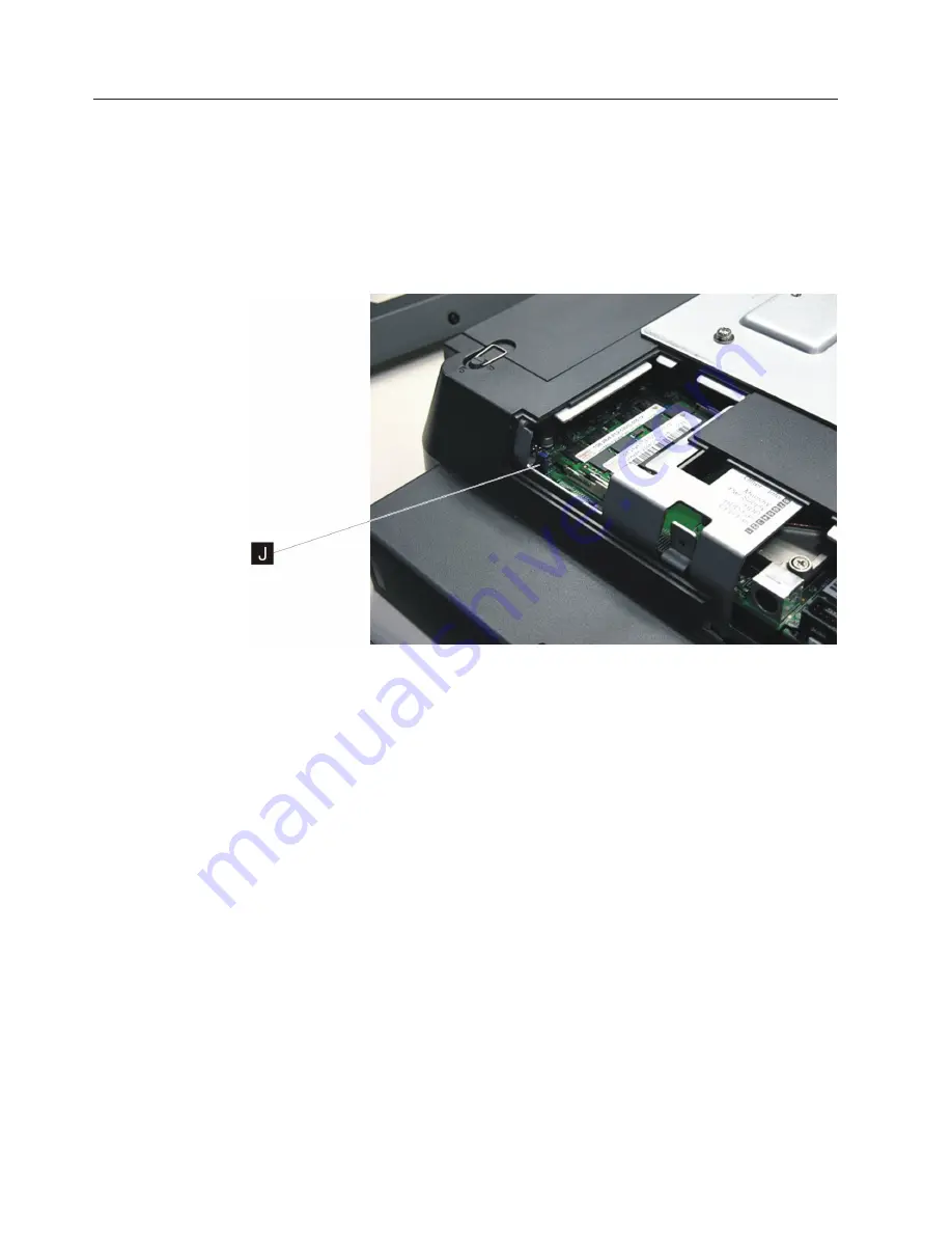
Follow these steps to locate and reset the CMOS jumper:

1.

Switch OFF the power to the IBM AnyPlace Kiosk. Unplug the power cord
from the external power source.

2.

Attention:

Establish personal grounding before touching this unit. See

“Electrostatic discharge” on page 94.

3.

Remove the side access door by loosening the captured screw.

4.

Locate the blue CMOS jumper near the memory card. See

J

in Figure 29.

5.

Remove the jumper and place it on the adjacent pins and leave for 10 seconds.

6.

Reinstall the jumper to the original position to reset defaults.

7.

Install the side door, and tighten the screw.

Note:

Do not over tighten the screw.

Figure 29. Location of the CMOS jumper

Removing and replacing FRUs

48

IBM AnyPlace Kiosk 4838

Summary of Contents for AnyPlace Kiosk 4838 Model 5 Series

Page 1: ...IBM AnyPlace Kiosk 4838 Planning Installation and Service Guide for Models 5xx 7xx and 9xx GA27 4369 01...

Page 2: ......

Page 3: ...IBM AnyPlace Kiosk 4838 Planning Installation and Service Guide for Models 5xx 7xx and 9xx GA27 4369 01...

Page 4: ...il store support A form for reader s comments is also provided at the back of this publication If the form has been removed address your comments to IBM Corporation Retail Store Solutions Information...

Page 5: ...r 4 Removing and replacing FRUs 35 Reviewing the IBM AnyPlace Kiosk assembly 36 Before you begin 38 Removing the rear cover 39 Removing the backlight inverter card 39 Removing the hard disk drive asse...

Page 6: ...unications statement 93 Taiwanese Class A warning statement 94 Taiwan contact information 94 Cable ferrite requirement 94 Electrostatic discharge 94 Product recycling and disposal 95 Battery return pr...

Page 7: ...dimensions provides precise product size information for all models and features v Appendix C Notices provides legal emission and country specific information v Appendix D Safety information provides...

Page 8: ...This site contains additional information that is gathered from field experience and not available when this document was developed vi IBM AnyPlace Kiosk 4838...

Page 9: ...f the accessibility features v All controls are located on the front of the system in easy reach v Industry standard serial and USB ports allow alternative I O devices v Manuals are available in PDF f...

Page 10: ...viii IBM AnyPlace Kiosk 4838...

Page 11: ...08 Updates for this release include the following v Light Path LEDs label v xFlash version for the BIOS March 2008 v Wireless notice updates v Procedural changes for 19 monitor v Part number updates v...

Page 12: ...x IBM AnyPlace Kiosk 4838...

Page 13: ...OS applications The second generation of the AnyPlace Kiosk provides more expansion capability through the USB and serial ports secondary VGA port headphone and microphone jacks and ExpressCard slot C...

Page 14: ...40 6 mm 17 35 in Depth 72 8 mm 2 87 in 78 3 mm 3 08 in 82 8 mm 3 26 in Weight 6 45 kg 14 2 lbs 8 27 kg 18 2 lbs 9 31 kg 20 5 lbs Note See Appendix B Product dimensions on page 81 for more detailed dim...

Page 15: ...nabled Super I O controller UART universal asynchronous receiver transmitter support with SMSC semiconductor solution Presence sensor Infrared presence detection Security v Trusted Platform Module v 1...

Page 16: ...02 11 a b g n draft with integrated antennas Note The wireless solution is certified for use only in certain countries See Appendix C Notices on page 89 Mounting options Tabletop mount Wall mount Expr...

Page 17: ...ole enables the mount to be secured B in Figure 2 with an M5 or 10 24 pan head screw Diagnostics The IBM AnyPlace Kiosk 4838 provides a diagnostic processor with Light Path LEDS to easily help isolate...

Page 18: ...d for Point of Sale WEPOS v Windows XP Service Pack SP 2 or higher v Windows Vista Business For guidance on installing any of the previous operating systems see the IBM AnyPlace Kiosk Operating System...

Page 19: ...ums Ensure that the cooling vents are not blocked by papers signs or other items Power usage Table 5 shows the power consumption for the IBM AnyPlace Kiosk Table 5 Power usage Description Amounts Powe...

Page 20: ...8 IBM AnyPlace Kiosk 4838...

Page 21: ...ace Kiosk This section describes procedures for setting up the IBM AnyPlace Kiosk product You should be familiar with the rear doors and connectors of the IBM 4838 before you begin the installation st...

Page 22: ...0 mm x 100 mm 3 93 in x 3 93 in mounting Note These holes allow for the standard M4 X 10 mm screws specified by the VESA standard F MSR mounting hole that is shared with I G Quarter turn latches H Rea...

Page 23: ...connector used by either the AC adapter or the AnyPlace POS Hub D Microphone E Headphone F VGA output G Scanner H Ethernet I RS 232 connectors 2X J Headphone K USB port L Power button Green indicates...

Page 24: ...unt on page 23 or the third party VESA mount instructions 4 Power On the IBM 4838 See Powering on on page 23 Opening the cable covers The cable covers provide security and protection to the IBM 4838 c...

Page 25: ...retaining the cable ties Install the cable ties as follows 1 Plug each cable into its respective connector 2 Attach the cable ties to the I O cables on the outside of the bottom cover The cable tie wi...

Page 26: ...the scanner 1 From the rear of the IBM AnyPlace Kiosk open both cable covers using the quarter turn latches 2 Align the scanner with the screw hole A in Figure 6 and secure the captured screw B 3 Con...

Page 27: ...being careful not to pinch the MSR cable 5 Install the screw or thumbscrew to retain the MSR Use the screw when the kiosk operates in a public environment so as to increase the security of the unit 6...

Page 28: ...n the captured screw on the side access door A in Figure 8 and slide out in the direction shown to remove A Figure 8 Removing the side access door Installing the IBM AnyPlace Kiosk 16 IBM AnyPlace Kio...

Page 29: ...9 and support post G and latch it into place 3 Replace the side door by tightening the captured screw Note Do not overtighten the screw F G Figure 9 Location of the flash drive Installing the IBM Any...

Page 30: ...IBM system unit For more information see the IBM AnyPlace POS Hub Planning Installation and Service Guide GA27 4370 Complete the following instructions to attach I O devices to the AnyPlace POS Hub 1...

Page 31: ...to the USB port directly adjacent to the power input port and to the IBM AnyPlace Kiosk 3 Connect the power cord of the AnyPlace POS Hub to an external power source 4 Power on IBM AnyPlace Kiosk and...

Page 32: ...t the hard drive until the hard drive is latched into place 3 Close hard drive door and fasten the captured screw Note Do not over tighten the screw Installing additional memory Follow these instructi...

Page 33: ...indicating that the memory card is retained The memory should appear aligned relative to the connector not angled crooked or misaligned 5 Install the side access door and fasten the captured screw No...

Page 34: ...ular to the base of the mount See picture 2 in Figure 14 3 Remove the base cover and upper cover 4 Route and connect the cables to the IBM 4838 5 Retain the cables see Retaining the cables on page 13...

Page 35: ...to secure the mount The lock slot is located under the base cover Wall mount Follow the procedures described in Chapter 3 Mounting the IBM AnyPlace Kiosk to the wall on page 27 Powering on The follow...

Page 36: ...or minus keys see M and N in Figure 15 Installing the control button cover To install the control button cover follow these steps 1 While facing the LCD insert the hinge pin on the left side first th...

Page 37: ...screw specification Screw thread Metric M3x0 5 Screw length 5 5 to 7 mm extension into the unit Screw head type Pan head button head cheese head or similar Screw head washer outside diameter 6 mm max...

Page 38: ...Installing the IBM AnyPlace Kiosk 26 IBM AnyPlace Kiosk 4838...

Page 39: ...ore mounting the wall mount plate ensure that you are following all applicable building and electric codes and accessibility requirements and guidelines When mounting ensure that you have enough room...

Page 40: ...th and length of the unit This recommendation reduces the risk that someone can accidentally walk into and damage the device Local laws governing the safety of individuals might require this type of c...

Page 41: ...s It is imperative that you attach the wall mount plate securely and permanently to the wall The 4838 weighs up to 9 5 kg 21 lb and its weight is centered approximately 75 mm 3 in away from the wall m...

Page 42: ...stener selection and installation follow the fastener manufacturer s recommendations Mounting to hollow walls Hollow walls include walls that are constructed of drywall board that is securely fastened...

Page 43: ...it might become loose if it is struck with a high force The drywall must be at least 12 7 mm 0 5 in thick to use this method Use a bubble level to assure that you mount the wall mount plate squarely I...

Page 44: ...e of laying bricks and the variation in types of mortar joints most brick walls have an uneven surface If possible select a location on the wall that allows all four corner screw holes to remain flat...

Page 45: ...Hollow Wall Anchor Screw size 5 mm 3 16 in nominal thread diameter Note Metal casing size is dependent on wall board thickness During installation grip head of metal casing with pliers when initially...

Page 46: ...Mounting the IBM AnyPlace Kiosk to the wall 34 IBM AnyPlace Kiosk 4838...

Page 47: ...Chapter 4 Removing and replacing FRUs Note Procedures in this section should be performed by qualified service personnel Copyright IBM Corp 2007 2008 35...

Page 48: ...embly Figure 19 on page 37 summarizes the field replaceable parts of the IBM 4838 assembly The part number associated with each FRU is located in Appendix A Field replaceable units Removing and replac...

Page 49: ...an Assembly Scanner Backlight inverter card Bottom cover Control buttons Button cover Card control Speakers Antenna top gray Antenna side black Antenna top white HDD assembly LCD shield LCD assembly F...

Page 50: ...e safety first Before removing the rear cover or performing any removal procedures follow these steps 1 Power off 2 Remove the power cable 3 Place the unit on a sturdy surface Removing and replacing F...

Page 51: ...ce the cover follow these steps 1 Place the unit face down on a steady surface and align the back cover approximately 8 mm 0 3 in lower than the top cover see Figure 20 2 Firmly slide the back cover t...

Page 52: ...e backlight card 4 Remove the two screws S that hold the backlight inverter card T 5 Remove card to access and detach the two or four LCD backlight cables 6 Lift the card to remove 7 To replace revers...

Page 53: ...20 3 Remove the hard disk drive assembly by pressing the drive bracket D in Figure 22 downward on the latch in the area marked in blue while pulling the bracket outward Note The HDD assembly might in...

Page 54: ...ove the hard disk drive Removing the hard disk drive assembly on page 41 to access and remove the tape securing the connector wires 4 Detach the HDD fan connector from the system board and remove the...

Page 55: ...bly in the order that they are numbered 1 through 5 4 Unplug the fan cable and lift out the CPU fan sink assembly Note To replace the processor go to Removing the processor on page 44 To replace follo...

Page 56: ...ribed in Removing the CPU fan sink assembly on page 43 3 Using a small flat blade screwdriver turn the screw H in Figure 25 that holds the processor 180 one half turn to release it Note The lock and u...

Page 57: ...2 From the rear of the IBM AnyPlace Kiosk open the cable cover using the two one quarter turn latches See Figure 5 on page 12 3 Disconnect the scanner cable from the scanner port 4 Loosen the screw B...

Page 58: ...scanner bottom cover assembly 3 Remove the scanner window taking note of the window orientation Note Avoid touching the inside of the scanner window so as not to leave dust or finger prints 4 To repla...

Page 59: ...cable cover by rotating it downward then sliding it to the right 3 To replace place the main cable cover post into the slot on the right side 4 Hold both the MSR USB cover and the main cable cover to...

Page 60: ...atic discharge on page 94 3 Remove the side access door by loosening the captured screw 4 Locate the blue CMOS jumper near the memory card See J in Figure 29 5 Remove the jumper and place it on the ad...

Page 61: ...o the IBM AnyPlace Kiosk Unplug the power cord from the external power source 2 Loosen the captured screw holding the side access door 3 Gently pull outward on the two side latches holding the memory...

Page 62: ...remove the memory card remove the rear cover see Removing the rear cover on page 39 4 To replace the memory card reverse these steps Note Do not over tighten the side door screw Removing and replacin...

Page 63: ...ce 2 Remove the rear cover as described in Removing the rear cover on page 39 3 Locate the battery on the system board B in Figure 31 4 Using your finger press on one of the tabs holding the coin batt...

Page 64: ...2 Locate the flash drive connector F in Figure 32 and lift up to remove the plug in flash drive F G Figure 32 Location of the flash drive Removing and replacing FRUs 52 IBM AnyPlace Kiosk 4838...

Page 65: ...tured screws A that hold the system board 7 Detach the control card cable and LCD LVDS cable Both are located on the back side of the system board 8 Remove the following components from the defective...

Page 66: ...gree to the terms 5 Click on Utilities 6 Click on VPD 7 Update the relevant VPD information d Check the Light Path LED s firmware level 1 Power on the system 2 After POST a screen appears for the IBM...

Page 67: ...Switch OFF the power to the IBM AnyPlace Kiosk Unplug the power cord from the external power source 2 If installed remove the MSR see Installing the MSR on page 15 3 Open the front cover touch assemb...

Page 68: ...See Figure 34 on page 55 5 Unlatch the touch cable as follows See Figure 35 Disconnect the touch cable by moving the connector lever to the open position and lifting out the cable Note See the Open an...

Page 69: ...llow the steps in Removing the front cover touch assembly on page 55 to remove the front assembly 3 Remove the two screws W in Figure 36 that retain each speaker and lift to remove 4 Detach each speak...

Page 70: ...ol card in place and lift out the card 4 Disconnect the two speaker cables and the control card cable from the rear of the control card 5 To replace reverse this procedure being sure to angle the card...

Page 71: ...6 To replace reverse this procedure Note Be sure to align the control button holes with the holes in the bottom cover Removing the LCD Follow these steps to remove the LCD 1 Switch OFF the power to th...

Page 72: ...side of the LCD shield and remove backlight cables two or four from the backlight inverter card 6 Gently lift up LCD to expose the LVDS cable underneath and disconnect it from the LCD Remove the LCD f...

Page 73: ...at the far left and right sides B in Figure 39 in the direction shown 3 Gently flex the hinge cover to un snap it from the mount 4 Remove the base cover C by pulling the cover in the direction shown 5...

Page 74: ...Removing and replacing FRUs 62 IBM AnyPlace Kiosk 4838...

Page 75: ...ledgebase You can determine if a product problem has been resolved Just review the symptoms and fixes in the knowledge base by performing the following steps 1 Go to the IBM Retail Stores Solutions Kn...

Page 76: ...nto the system board 3 Make sure that no obstacle is preventing the fan from spinning 3 HDD fan v The HDD temperature has exceeded 60 C v The fan is no longer spinning 4 HDD The HDD failed the hard di...

Page 77: ...ation LED 8 will not cause the hardware failure light to illuminate Using the system event log viewer The system event log viewer is a BIOS POST power on start plug in that provides access to the syst...

Page 78: ...mpts on the screen to view events or to clear the system event log Notes 1 All saved events can be viewed 2 Events are logged by event date most recent to oldest 3 If the event log reaches its capacit...

Page 79: ...Replace the system board The display is blank and the system is beeping 1 Check the system memory to ensure that the memory control card is seated properly 2 Replace the memory SO DIMM Touch display n...

Page 80: ...to resolve a problem go to Clearing the CMOS settings on page 70 and reset CMOS Clearing CMOS ensures that all BIOS settings are configured to a known functional state Using the CMOS Setup Utility Fo...

Page 81: ...and boot device settings and set the keyboard features Integrated peripherals Using this menu you can configure I O devices such as serial ports Ethernet parallel port USB controller and keyboard Pow...

Page 82: ...aring the CMOS settings Always reset CMOS as described at Restoring the default CMOS settings before replacing a system board to resolve a problem This practice allows you to determine if a corrupted...

Page 83: ...tility settings you can boot into the diagnostics using the USB memory key Insert the USB memory key and power on the system If you have previously changed the default settings go to Step 7 7 If you h...

Page 84: ...he target system 7 Power on the system and allow the system to boot from the memory key Note The BIOS setup boot order might need to be configured to boot from the USB memory key NOTE 8 After the upda...

Page 85: ...date executable to the target system or copy the update to memory key to be inserted in the target system 2 Boot the Windows operating system 3 Execute the BIOS update executable and follow the displa...

Page 86: ...abrasive microfiber cloth with isopropyl alcohol Attention Do not apply cleaning solution directly to the screen Always spray the cleaner on a clean cloth and then wipe the screen Cleaning solutions...

Page 87: ...Appendix A Field replaceable units Copyright IBM Corp 2007 2008 75...

Page 88: ...Assembly 1 IBM AnyPlace Kiosk 4838 1 2 4 3 5 6 7 8 9 10 12 13 14 15 16 17 18 19 20 21 22 23 24 25 26 27 28 29 11 Field replaceable units 76 IBM AnyPlace Kiosk 4838...

Page 89: ...d assembly 15 44V0775 1 Backlight inverter card 15 in LCD 15 44V0776 1 Backlight inverter card 17 in 19 in LCD 16 44V0717 1 Scanner line 16 44V0718 1 Scanner omni without scanner shield 16 44V0719 1 S...

Page 90: ...1 Bracket AC adapter wall mount 44V0710 1 Mount tabletop includes VESA adapter plate and installation instructions 44V0716 1 Mount wall 44V0714 1 Tabletop mount cover kit includes all 5 plastic cover...

Page 91: ...former Yugoslav Republic of Madagascar Mali Martinique Mauritania Mauritius Mayotte Moldova Republic of Monaco Mongolia Morocco Mozambique Netherlands New Caledonia Niger Norway Poland Portugal Reunio...

Page 92: ...Field replaceable units 80 IBM AnyPlace Kiosk 4838...

Page 93: ...mm 14 47 in 402 0 mm 15 83 in 78 3 mm 3 08 in 8 27 kg 18 2 lbs _ System with 19 in LCD 398 5 mm 15 69 in 440 6 mm 17 35 in 82 8 mm 3 26 in 9 31 kg 20 5 lbs 3 track MSR NA Adds 43 9 mm 1 73 in NA 0 18...

Page 94: ...48 00 93 30 38 55 2X 3 80 16 90 127 00 22 30 16 20 166 20 Figure 44 AC power adapter wall mount bracket Product dimensions 82 IBM AnyPlace Kiosk 4838...

Page 95: ...utton cover 48 2 63 2 14 4 52 8 71 1 60 Figure 45 15 in system unit with features 433 65 33 95 108 04 286 64 44 72 129 18 438 32 277 00 145 52 62 12 31 46 393 87 433 84 121 40 210 00 79 30 LCD Center...

Page 96: ...9 147 04 185 09 33 62 6 50 120 28 13 41 84 24 33 45 72 80 325 64 31 95 344 39 77 17 69 32 141 77 6 50 100 00 50 90 100 00 15 00 6 50 40 12 15 00 M4 screw for mounting M3 screw for accessories M3 screw...

Page 97: ...on cover 8 9 52 8 71 1 60 66 1 88 3 Figure 49 17 in system unit without features LCD Center 210 00 96 13 95 85 107 75 307 15 28 45 277 00 475 25 479 94 474 54 112 44 429 06 47 01 148 83 40 57 72 130 7...

Page 98: ...98 168 13 201 93 56 60 6 50 169 11 44 55 77 01 38 95 78 30 367 53 31 63 340 18 97 68 31 84 149 45 100 00 49 20 100 00 6 50 5 51 46 43 77 01 M4 screw for mounting M3 screw for accessories M3 screw for...

Page 99: ...66 3 Button cover 4 4 52 8 71 1 60 66 1 119 1 Figure 53 19 in system unit with features LCD Center 210 00 115 58 115 06 107 51 322 29 23 95 277 00 506 01 510 77 504 76 106 23 455 33 66 78 151 54 40 54...

Page 100: ...1 38 183 75 398 53 43 35 82 80 340 18 19 LCD Center 100 00 49 20 6 50 100 00 12 83 206 53 49 17 46 26 70 35 87 36 M4 Screw for Mounting 6 50 34 49 31 39 M3 Screw For Accessories M4 Screw for Accessori...

Page 101: ...Trade Asia Corporation Licensing 2 31 Roppongi 3 chome Minato ku Tokyo 106 Japan The following paragraph does not apply to the United Kingdom or any other country where such provisions are inconsisten...

Page 102: ...ducts and cannot confirm the accuracy of performance compatibility or any other claims related to non IBM products Questions on the capabilities of non IBM products should be addressed to the supplier...

Page 103: ...t 15 of the FCC Rules Operation is subject to the following two conditions 1 This device may not cause harmful interference and 2 This device must accept any interference received including interferen...

Page 104: ...en nach EN 50082 1 und EN 55022 Klasse A EN 55022 Klasse A Ger te m ssen mit folgendem Warnhinweis versehen werden Warnung dies ist eine Einrichtung der Klasse A Diese Einrichtung kann im Wohnbereich...

Page 105: ...s equipment is used in a domestic environment radio interference may occur in which case the user may be required to take corrective actions Japan Electronics and Information Technology Industries Ass...

Page 106: ...ion Electrostatic discharge ESD damage can occur when there is a difference in charge between the part the product and the service person No damage will occur if the service person and the part being...

Page 107: ...ponsablemente sus equipos cuando stos ya no les sean tiles IBM dispone de una serie de programas y servicios de devoluci n de productos en varios pa ses a f n de ayudar a los propietarios de equipos a...

Page 108: ...s and regulations Battery return program This product may contain sealed lead acid nickel cadmium nickel metal hydride lithium or lithium ion battery Consult your user manual or service manual for spe...

Page 109: ...rebut mais plut t r cup r e en fin de cycle de vie selon cette norme In accordance with the European Directive 2006 66 EC batteries and accumulators are labeled to indicate that they are to be collec...

Page 110: ...vironmental Quality site at www deq state or us lq electronics htm Washington For information about recycling covered electronic devices in the State of Washington go to the Department of Ecology Webs...

Page 111: ...este produto leia as informa es de seguran a contidas em Informa es Sobre Segurana a Leia Isto Primeiro GA27 4004 Esse folheto descreve procedimentos de seguran a para a instala o de cabos e conex es...

Page 112: ...te zuerst lesen GA27 4004 Diese Ver ffentlichung beschreibt die Sicherheitsvorkehrungen f r das Verkabeln und Anschlie en elektrischer Ger te Vigy zat Miel tt megkezdi a berendez s zembe helyez s t ol...

Page 113: ...uar de um modo seguro as liga es el ctricas dos equipamentos Peligro Antes de empezar a instalar este producto lea la informaci n de seguridad en Informaci n de Seguridad Lea Esto Primero GA27 4004 Es...

Page 114: ...IBM IBM GA27 4004 GA27 4004 Safety information 102 IBM AnyPlace Kiosk 4838...

Page 115: ...GA27 4004 GA27 4004 GA27 4004 GA27 4004 GA27 4004 GA27 4004 IBM Safety information Appendix D Safety information 103...

Page 116: ...Safety information 104 IBM AnyPlace Kiosk 4838...

Page 117: ...T MAXIMUM OUTPUT CLASS 2 LASER PRODUCT SCAN RATE 600 scans sec IEC 60825 1 A2 2001 Date Complies with 21CFR 1040 10 and 1040 11 except for deviations pursuant to Laser Notice No 50 dated July 26 2001...

Page 118: ...eseen C029 ATTENTION Ce produit contient un laser de classe 2 Evitez de regarder fixement le faisceau C029 Achtung Dieses Produkt enth lt einen Laser der Klasse 2 Niemals direkt in den Laser strahl bl...

Page 119: ...d 2 this device must accept any interference received including interference that may cause undesired operation This wireless adapter does not contain any user serviceable components Any unauthorized...

Page 120: ...nction with any other antenna or transmitter during customer usage Interference statement An improper installation or unauthorized use may cause harmful interference to radio communications Also any t...

Page 121: ...u m me si ce brouillage est susceptible de compromettre le fonctionnement du dispositif Exposure of humans to RF fields RSS 102 IBM Anyplace Kiosk 4838 computers employ low gain integral antennas that...

Page 122: ...erved at f lgende udstyr IBM 802 11 a b g n wireless LAN mini PCI adapter overholder de v sentlige krav og vrige relevante krav i direktiv 1999 5 EF Hierbij verklaart Atheros Communications Inc dat he...

Page 123: ...mit den grundlegenden Anforderungen und den anderen relevanten Festlegungen der Richtlinie 1999 5 EG Atheros Communications Inc IBM 802 11 a b g n wireless LAN mini PCI adapter 1999 5 Atheros Communic...

Page 124: ...e ale ot r rii Guvernului nr 88 2003 Directivei 1999 5 EC Atheros Communications Inc t mto vyhlasuje e tento IBM 802 11 a b g n wireless LAN mini PCI adapter vyhovuje technick m po iadavk m a al m ust...

Page 125: ...alueella ja Sveitsiss Avis important Appareil r seau radio IBM 802 11 a b g n wireless LAN mini PCI adapter faible puissance fonctionnant dans la bande 2 4 5 GHz en int rieur et en environnement priv...

Page 126: ...vej IBM 802 11 a b g n wireless LAN mini PCI adapters n zkym v konom na prev dzku v p sme 2 4 5 GHz pre dom ce a kancel rske prostredie v EEA a vaj iarsku Pomembno obvestilo Radijski IBM 802 11 a b g...

Page 127: ...Kiosk notices Appendix E Kiosk notices 115...

Page 128: ...Croatia wireless certification documents Kiosk notices 116 IBM AnyPlace Kiosk 4838...

Page 129: ...Kiosk notices Appendix E Kiosk notices 117...

Page 130: ...Kiosk notices 118 IBM AnyPlace Kiosk 4838...

Page 131: ...tifies a register a particular part of storage or some other data source or destination A 3 To refer to a device or an item of data by its address I A 4 The location in the storage of a computer where...

Page 132: ...ction of related data records organized in a specific manner for example a payroll file one record for each employee showing such information as rate of pay and deductions or an inventory file one rec...

Page 133: ...ers On a token ring network a frame is created from a token when the token has data appended to it On a token bus network IBM PC Network all frames including the token frame contain a preamble start d...

Page 134: ...and parameters between separate portions of the computer program 4 To interconnect items of data or portions of one or more computer programs 5 In SNA the combination of the link connection and link s...

Page 135: ...ing system or a program telling the operator to perform a specific function or informing the operator of a specific condition within the system such as an error condition option 1 A specification in a...

Page 136: ...e that examines the bar code on merchandise tickets credit cards and employee badges and generates analog or digital signals corresponding to the bar code serial port On personal computers a port used...

Page 137: ...Serial Bus USB powered A powered USB connector provides additional power from the host system A powered USB receptacle consists of two connectors stacked vertically inside the common housing The upper...

Page 138: ...126 IBM AnyPlace Kiosk 4838...

Page 139: ...ary checklist 63 diagnostic processor using 64 diagnostics 5 disability vii display blank 67 not responding to touch 67 disposal of equipment 95 E electronic emissions notices 91 Australia and New Zea...

Page 140: ...ssor 43 LCD 59 memory card 49 mounting stand cover set 60 processor 44 rear cover 39 scanner and scanner window 45 speakers 57 system board 53 removing FRUs 35 replacing FRUs 35 requirements wall moun...

Page 141: ...9 77 44V0743 1 9 77 44V0746 1 11 77 44V0747 1 11 77 44V0750 1 78 44V0751 1 78 44V0752 1 78 44V0753 1 78 44V0754 1 8 77 44V0756 1 11 77 44V0757 1 4 77 44V0758 1 3 77 44V0759 1 10 77 44V0760 1 28 77 44V...

Page 142: ...130 IBM AnyPlace Kiosk 4838...

Page 143: ...nformation about products and prices please contact your IBM branch office your IBM business partner or your authorized remarketer When you send comments to IBM you grant IBM a nonexclusive right to u...

Page 144: ...opment Dept ZBDA P O Box 12195 RESEARCH TRIANGLE PARK NC 27709 9990 _ _ _ _ _ _ _ _ _ _ _ _ _ _ _ _ _ _ _ _ _ _ _ _ _ _ _ _ _ _ _ _ _ _ _ _ _ _ _ _ _ _ _ _ _ _ _ _ _ _ _ _ _ _ _ _ _ _ _ _ _ _ _ _ _ _...

Page 145: ......

Page 146: ...GA27 4369 01...

Reviews: