12
IBM eServer OpenPower 710 Technical Overview and Introduction
monitor. A minimum of one LCM feature (FC 4268) or USB feature (FC 4269) is required with
a Netbay LCM Switch (FC 4202). Each feature can support up to four systems. When
connecting to an OpenPower 710 server, FC 4269 provides connection to the POWER5 USB
ports. Only the PS/2 keyboard is supported when attaching the 7316-TF3 to the LCM Switch.
The following should be considered when selecting the LCM Switch:
The KCO cable (FC 4268) is used with systems with PS/2 style keyboard, display, and
mouse ports.
The USB cable (FC 4269) is used with systems with USB keyboard or mouse ports.
The switch offers four ports for server connections. Each port in the switch can connect a
maximum of 16 systems.
– One KCO cable (FC 4268) or USB cable (FC 4269) is required for every four systems
supported on the switch.
– A maximum of 16 KCO cables or USB cables per port may be used with the Netbay
LCM Switch (FC 4202) to connect up to 64 servers.
Hardware Management Console 7310 Model CR3
The 7310 Model CR3 Hardware Management Console (HMC) is a 1U, 19-inch
rack-mountable drawer supported in the 7014 Model T00 and T42 racks. For additional HMC
specifications see “Hardware Management Console” on page 33.
1.6.6 OEM rack
The OpenPower 710 server can be installed in a suitable OEM rack, provided that the rack
conforms to the EIA-310-D standard for 19-inch racks. This standard is published by the
Electrical Industries Alliance, and a summary of this standard is available in the publication
IBM
Eserver
Planning, SA38-0508.
The key points mentioned in this documentation are as follows:
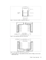
The front rack opening must be 451 mm wide + 0.75 mm (17.75 0.03 inches),
and the rail-mounting holes must be 465 mm + 0.8 mm (18.3 0.03 inches) apart
on center (horizontal width between vertical columns of holes on the two front-mounting
flanges and on the two rear-mounting flanges). See Figure 1-4 for a top view showing
specifications dimensions.
The vertical distance between mounting holes must consist of sets of three holes spaced
(from bottom to top) 15.9 mm (0.625 inches), 15.9 mm (0.625 inches), and 12.67 mm
(0.5 inches) on center (making each three-hole set of vertical hole spacing 44.45 mm
(1.75 inches) apart on center). Rail-mounting holes must be 7.1 mm + 0.1 mm
(0.28 0.004 inches) in diameter. See Figure 1-5 and Figure 1-6 for top and
bottom front specification dimensions.
Note: A server microcode update may be required on installed systems for boot-time SMS
menu support of the USB keyboards. The update may also be required for the LCM switch
on the 7316-TF3 console (FC 4202). Microcode updates are located at the URL below.
http://techsupport.services.ibm.com/server/mdownload
We recommend that you have the 7316-TF3 installed between EIA 20 to 25 of the rack for
ease of use. The 7316-TF3 or any other graphics monitor requires a POWER GXT135P
graphics accelerator (FC 2849) to be installed in the server, or other graphic accelerator, if
supported.
Summary of Contents for 9123710 - eServer OpenPower 710
Page 2: ......
Page 68: ...58 IBM eServer OpenPower 710 Technical Overview and Introduction ...
Page 69: ......


