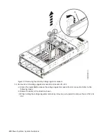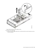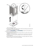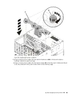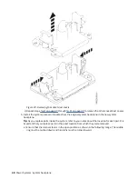
Figure 32. Removing the heat sink
b) Grip the heat sink (B) on opposing sides and remove the heat sink by lifting it upward. Set the heat
sink aside with the module side facing upward.
c) Repeat steps “17.a” on page 32 through “17.b” on page 33 to remove the remaining heat sinks.
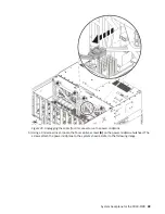
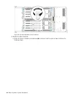
18. Remove the system processor modules.
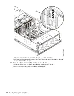
a) Use tweezers to remove the thermal interface material (TIM) from the system processor module.
Discard the TIM after you remove it.
Important: The TIM cannot be reused. The replacement system backplane kit includes new TIM.
b) Open the system processor module tray packages, which were included with the replacement
system backplane kit.
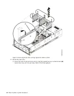
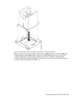
c) Place the bottom of the system processor module tray on an appropriate ESD surface so that the
guide pins face upwards, as shown in the following figure.
System backplane for the 9040-MR9 33
Summary of Contents for 9040-MR9
Page 1: ...Power Systems System backplane for the 9040 MR9 IBM...
Page 4: ...iv...
Page 14: ...xiv Power Systems System backplane...
Page 17: ...or or or or System backplane for the 9040 MR9 3...
Page 98: ...84 Power Systems System backplane...
Page 109: ......
Page 110: ...IBM...


