


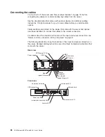


Connecting
the
cables
You
must
turn
off
the
server
(see
“Server
power
features”
on
page
12)
before
connecting
any
cables
to
or
disconnecting
any
cables
from
the
server.
See
the
documentation
that
comes
with
optional
devices
for
additional
cabling
instructions.
It
might
be
easier
for
you
to
route
cables
before
you
install
certain
options.
Cable
identifiers
are
printed
on
the
cables
that
come
with
the
server
and
options.
Use
these
identifiers
to
connect
the
cables
to
the
correct
connectors.
For
details
about
the
location
and
function
of
the
input
and
output
connectors,
see
“Server
controls,
connectors,
LEDs,
and
power”
on
page
8.
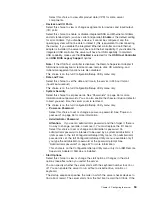
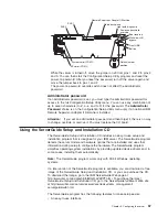
The
following
illustrations
show
the
locations
of
the
input
and
output
connectors
on
the
server.
Detailed
cabling
instructions
are
in
the
Rack
Installation
Instructions
that
come
with
the
server.
Rear
view
SP serial
System serial
Keyboard
Mouse
SP Ethernet 10/100
Gigabit Ethernet 2
Gigabit Ethernet 1
USB 1
USB 2
IXA RS 485
Power-supply
Video
Front
view
Power-control button
Power-on LED
USB connector
Hard disk drive activity LED
Information LED
System-error LED
Locator LED
Release latch
48
IBM
System
x3850
Type
8864:
User’s
Guide
Summary of Contents for 88632SU
Page 1: ...IBM System x3850 Type 8864 User s Guide...
Page 2: ......
Page 3: ...IBM System x3850 Type 8864 User s Guide...
Page 26: ...14 IBM System x3850 Type 8864 User s Guide...
Page 62: ...50 IBM System x3850 Type 8864 User s Guide...
Page 88: ...76 IBM System x3850 Type 8864 User s Guide...
Page 90: ...78 IBM System x3850 Type 8864 User s Guide...
Page 99: ......
Page 100: ...Part Number 31R1881 Printed in USA 1P P N 31R1881...


