


Handling the Module
The module can be easily damaged by electrostatic dis-
charge. To prevent damage, observe the following:
■
Do not remove the module from its packaging until
you are ready to install it into a Switch.
■
Do not touch any of the pins, connections or
components on the module.
■
Handle the module only by its edges and front panel.
■
Always wear an anti-static wristband connected to a
suitable earth point.
■
Always store or transport modules in anti-static
packaging.
Installing the Module into a Switch
ATTENTION
:
When a module is installed into a
Switch, the Switch only supports one port trunk. If you
have two port trunks configured on your Switch, remove
one of them before installing the module. If you do not
remove the second port trunk, both port trunks are
automatically removed.
1
Ensure that the Switch is disconnected from the mains
power supply and that you are wearing an anti-static
wristband connected to a suitable earth point.
2
Place the Switch on a flat surface. Using a suitable screw-
driver, remove the blanking plate from the rear of the
Switch. Do not remove any other screws from the rear of
the Switch.
3
Keep the blanking plate and screws in a safe place. If you
remove the module at any time, you must replace the
blanking plate to prevent dust and debris entering the
Switch and to aid the circulation of cooling air.
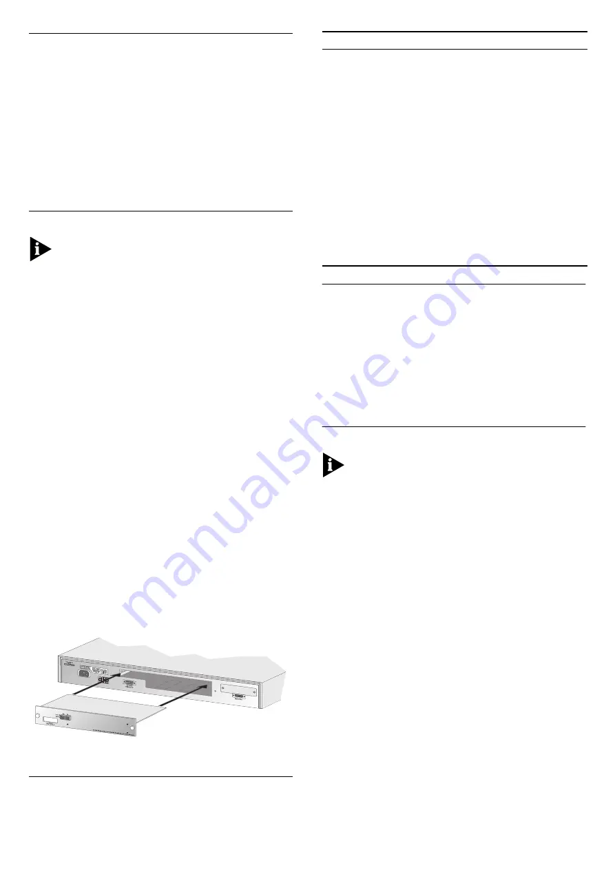
4
Hold the module so that the text on the front panel is
upright, and insert it into the Switch, ensuring the connec-
tors are fully engaged. Tighten the two captive thumb-
screws securing the module.
5
Install the module:
a
Ensure that the Switch is powered-up.
b
Remove the protective plastic covers from the fiber
connections on the module.
c
Plug the SC connector on the fiber cable into the fiber
socket on the module.
d
Connect the other end of the fiber optic segment to a
device fitted with a Gigabit Ethernet connection.
6
Check the LEDs on the front of the Switch to ensure that
the module is operating correctly. Refer to “Statement of
Limited Warranty” on page 6 for more information.
Figure 1
Inserting the module into the switch
LEDs
You can gather information about the status of the
module and its packet activity using LEDs on the front of
the Switch and on the module itself.
Removing the Module from a Switch
1
Ensure that the power supply and the fiber backbone con-
nection cables are disconnected from the Switch.
2
Place the Switch on a flat surface. Undo the two captive
thumbscrews securing the module into the Switch. Do not
remove any other screws from the Switch.
3
If you are not fitting another module immediately, you
must replace the blanking plate to ensure that dust and
debris do not enter the Switch and to aid the circulation of
cooling air.
Managing the Module
The module requires management software version 2.0
or later to be installed on the Switch. For instructions on
upgrading management software, refer to the documen-
tation supplied with your Switch.
When the module is installed in a suitable Switch, the
Switch interfaces contain features to enable, disable and
monitor the auto-negotiation system specified in the
IEEE 802.3z Gigabit Ethernet standard. This system allows
the module port to automatically detect the flow control
setting of a Gigabit Ethernet link and provide the appro-
priate connection.
Configuring IEEE 802.3z Auto-negotiation Using the
Web Interface
You can enable and disable IEEE 802.3z auto-negotiation
for the module port using the Port Setup page of the
web interface.
To do this:
1
Click the Unit icon on the side-bar.
2
Click the module port on the Switch graphic. The Port
Setup page is displayed.
3
From the
Auto-negotiation
listbox, specify Enabled or Dis-
abled:
■
Specify Enabled if the device at the other end of the
link supports IEEE 802.3z auto-negotiation. This is the
default setting for the listbox.
■
Specify Disabled if the device at the other end of the
link does not support IEEE 802.3z auto-negotiation.
If you specify Disabled, the module port uses the
bypass mechanism and bi-directional flow control
specified in IEEE 802.3z. When using this setting, we
LED
Color
Indicates
Expansion Module Port Status LEDs
(located on the front of the Switch):
Packet
Yellow
Packets are being transmit-
ted/received on the module port.
Status
Yellow
Yellow flashing
Off
A valid module is installed.
An unrecognized module is
installed.
No module is installed.
Module Status LEDs
(located on the module at the rear of the Switch):
Packet
Yellow
Packets are being transmit-
ted/received on the module port.
Status
Green
Green flashing
(fast 1Hz)
Green flashing
(slow 0.5Hz)
Off
Link present and port enabled.
Link present but port disabled.
The module is failing to auto-nego-
tiate. See “Problem Solving”.
Link failed or disconnected.
2


