Systems
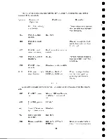
Sequence of
Operation
Conditions
Remarks
04D
Pick R4, clutch.
R7AL, R2 hold circuit
1/2 power to stop clutches
05E
Pick HD6, take-
up motor sta rt.
R5AU, R6BL, R7AUn/o
Start the take-up m otor.
Start raising the head
cover, and turning the
reels to pull tape from
the columns.
06G
Drop HD8.
R7AUn/c
The capstans remain r e
tracted because of the
mechanical latch.
05F
Pick R8, head
cover not down.
Head cover down m icro
switch.
Head cover has just
started up.
06H
Drop DP2, cap
stan mtr.
R8AUn/c
Stop the capstan motor.
02E
Manual start
line up.
R8BL
The unit is now in a fo r
ward-start status, placing
the moving pulleys away
from the stop capstans.
05G
Pick R9, RIO,
tape out of
columns.
Flapper valve m icro
switches.
Tape out of both columns.
04A
Hold R l, R18,
run.
R3AL
05F
Pick R12, high
speed DP3, re
wind mtr.
R llA U n /c, head cover
up microswitch, R10AU,
R9AU, R5BL, R6BLn/c,
R7AUn/o.
Indicates tape out of both
columns and head cover
all the way up.
05E
Stop take-up mtr.
R12BU
10.01
Remove power from
both stop clutches.
R12AL, BL
No power on any of the
six clutches.
10.02
Start the rewind
mtr.
DP3 A, B
Rewind tape at high speed
until 1/2 inch is left on
machine reel.
34
Summary of Contents for 727
Page 6: ......
Page 67: ...co Q...
Page 68: ......
Page 69: ...To Fuse 13 48V...
Page 70: ......
Page 71: ......
Page 72: ......
Page 73: ...o IC To Fuse 13 48V...
Page 74: ......
Page 75: ......
Page 76: ......
Page 78: ......
Page 92: ......
Page 93: ...039 0035 FIGURE 1 BIT PO SITIO N S O N TAPE CURRENT GENERATOR FIGURE 3c...
Page 95: ...w PATH OF TAPE THROUGH MACHINE FIGURE 6...
Page 97: ...SPLIT IDLER ASSEMBLY FIGURE 8...
Page 98: ......
Page 99: ...CLUTCH HOUSING POWDERED IRON AND GRAPHITE MIXTURE FIGURE 10 MAGNETIC CLUTCH...
Page 100: ...PUSH ROD DIAPHRAGM VACUUM COLUMN SWITCHES FIGURE II...
Page 101: ...BACKWARD MOTOR CAPSTAN MOTOR FORWARD MOTOR...
Page 102: ...LATCH FIGURE f3...
Page 103: ...140 140...
Page 107: ...FIGURE 18 HEAD ASSEMBLY A DJUSTM ENTS...
Page 108: ...TAPE C LEA N ER FIG URE 19...
Page 109: ...VACUUM COLUMN ADJUSTMENT FIG U RE 22...
Page 110: ...DRIVE MOTOR PULLEY CAPSTAN DRIVE BELT TENSION FIGURE 23 REAR VIEW S...
Page 113: ...CONTROL UNIT TAPE DRIVE TESTER FIGURE 28 TAPE DRIVE TESTER CO NN EC TIO N S...
Page 116: ...FIGURE 32 HIGH SPEED REWIND...
Page 135: ......
Page 136: ...v n...
Page 137: ......
Page 138: ......
Page 139: ......
Page 140: ......
Page 141: ......
Page 142: ......
Page 143: ......
Page 144: ......
Page 145: ......
Page 146: ......
Page 147: ......
Page 148: ......
Page 149: ......
Page 150: ......
Page 151: ......
Page 152: ......
Page 153: ......
Page 154: ......
Page 155: ......
Page 156: ......
Page 157: ......
Page 158: ......
Page 159: ......
Page 160: ......
Page 161: ......
Page 162: ......
Page 163: ......


