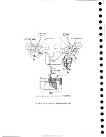
"re se t write triggers" pulse could coincide with the fall of a write pulse. In this case
(Case B, Figure 30) assuming all ones were being written, at time T^
some of the
write triggers might be turned on and some might be turned off. Then these triggers
would be flipping out of step with each other for the rest of that writing period. This
condition could be observed at the write trigger neons when the writing is stopped.
Usually, however, (as in Case A) all triggers are either on or off. Therefore,
observing the write trigger neons shows whether the triggers are operating properly.
1 9 .3 .3 Reading
To read a tape, set the read-w rite switch to READ and press the start button.
Tape moves forward in read status. The pre-am p output of the track selected by
the response select switch can be observed with a scope at the read bus hub. De
pressing the stop button stops the operation.
When in read status, the tape is read in start-stop fashion if the start-stop
switch is turned on. The start-stop frequency dial controls the frequency of starting
and stopping the tape. Unless the manual switch is used, tape cannot be read when
the tape indicator is on.
1 9 .3 .4 Auto Cycle
The auto cycle feature on the TDT may be used to check the following operations
of the tape drive: end-of-tape sensing, load-point sensing, high-speed rewind,
vacuum switches, and flapper valves. The function of the auto cycle feature is to
write the tape in a forward direction until an EOT reflective spot is sensed. The ma
chine then rewinds the tape back to the load point. Upon reaching the load point, the
tape unit starts writing again and the cycle is repeated.
This operation is accomplished in the following manner; upon sensing the EOT
reflective spot, the signal "s e l and TI on" goes through section E of the response
select switch and back to the tape drive as "rew in d ." This signal causes the tape
to rewind, and the signal "select unit rewinding" com es from the tape drive through
section D of the response select switch and returns to the tape drive as "reset T I,"
thus turning off the tape indicator. Section F of the response select switch discon
nects the "select and TI on" line that normally turns off the go-fb trigger. When the
tape is rewound to load point, the ready line com es up and the tape drive starts writ
ing again.
To put the machine into the auto cycle operation, the response select switch is
set to AUTO CYCLE and the read-w rite switch is set to WRITE. P ressing the start
button then puts the tape drive into auto-cycle operation. By placing the EOT reflective
spot a few feet from the load point, the cycle can be made very short and the load
point and EOT photo cells and single shots can be checked. If the EOT reflective spot
is placed farther back on the tape so that the tape drive can just go into high-speed
rewind upon sensing the spot, and the load point is placed just before this area, then
the operation of the vacuum system and associated switches can be observed at a
frequent rate.
With a full reel of tape on the tape drive and the EOT spot at the end of the tape,
the tape drive can be auto-cycled to check the rewinding of a full reel at high speed.
82
Summary of Contents for 727
Page 6: ......
Page 67: ...co Q...
Page 68: ......
Page 69: ...To Fuse 13 48V...
Page 70: ......
Page 71: ......
Page 72: ......
Page 73: ...o IC To Fuse 13 48V...
Page 74: ......
Page 75: ......
Page 76: ......
Page 78: ......
Page 92: ......
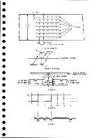
Page 93: ...039 0035 FIGURE 1 BIT PO SITIO N S O N TAPE CURRENT GENERATOR FIGURE 3c...
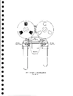
Page 95: ...w PATH OF TAPE THROUGH MACHINE FIGURE 6...
Page 97: ...SPLIT IDLER ASSEMBLY FIGURE 8...
Page 98: ......
Page 99: ...CLUTCH HOUSING POWDERED IRON AND GRAPHITE MIXTURE FIGURE 10 MAGNETIC CLUTCH...
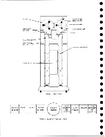
Page 100: ...PUSH ROD DIAPHRAGM VACUUM COLUMN SWITCHES FIGURE II...
Page 101: ...BACKWARD MOTOR CAPSTAN MOTOR FORWARD MOTOR...
Page 102: ...LATCH FIGURE f3...
Page 103: ...140 140...
Page 107: ...FIGURE 18 HEAD ASSEMBLY A DJUSTM ENTS...
Page 108: ...TAPE C LEA N ER FIG URE 19...
Page 109: ...VACUUM COLUMN ADJUSTMENT FIG U RE 22...
Page 110: ...DRIVE MOTOR PULLEY CAPSTAN DRIVE BELT TENSION FIGURE 23 REAR VIEW S...
Page 113: ...CONTROL UNIT TAPE DRIVE TESTER FIGURE 28 TAPE DRIVE TESTER CO NN EC TIO N S...
Page 116: ...FIGURE 32 HIGH SPEED REWIND...
Page 135: ......
Page 136: ...v n...
Page 137: ......
Page 138: ......
Page 139: ......
Page 140: ......
Page 141: ......
Page 142: ......
Page 143: ......
Page 144: ......
Page 145: ......
Page 146: ......
Page 147: ......
Page 148: ......
Page 149: ......
Page 150: ......
Page 151: ......
Page 152: ......
Page 153: ......
Page 154: ......
Page 155: ......
Page 156: ......
Page 157: ......
Page 158: ......
Page 159: ......
Page 160: ......
Page 161: ......
Page 162: ......
Page 163: ......


