background image

3.

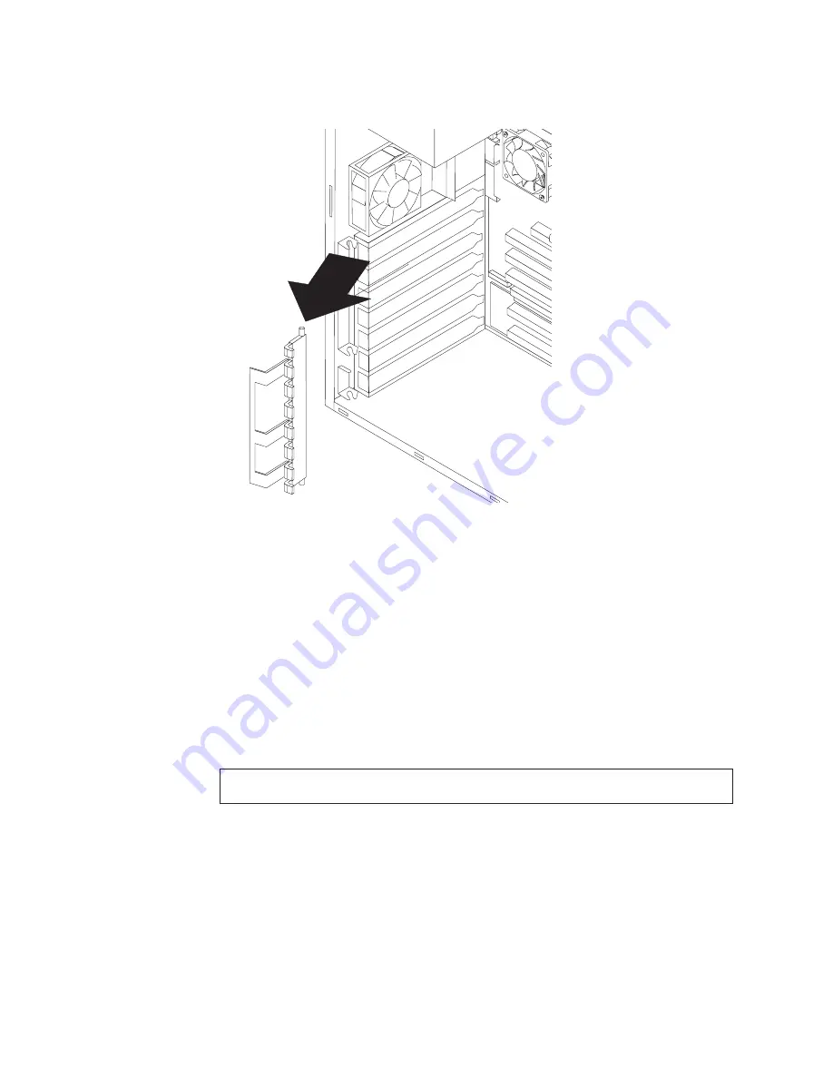
Disconnect all adapter cards from the system board and remove them from the
computer (see “Adapter installation” on page 66).

4.

Pull the adapter retainer away from the chassis.

5.

To install the adapter retainer, reverse the previous steps.

Bezel

To remove the main bezel on the tower model, do the following:

1.

Remove the side cover (see “Side cover removal” on page 63).

2.

Push the blue bezel release latch, located on the inside roof of the tower
chassis. The bezel will detach from the chassis.

3.

To install the bezel, align the tabs at the bottom of the bezel with the slots in
the lower front of the chassis; then press the top of the bezel against the chassis
until it clicks into place.

Bezel release latch

Note:

Read “Before you begin” on page 41 and the safety notices at “Safety notices

(multi-lingual translations)” on page 135.

94

Hardware Maintenance Manual: IBM IntelliStation E Pro Type 6204 and Type 6214

Summary of Contents for 621410U - IntelliStation E - Pro 6214

Page 1: ...Hardware Maintenance Manual IBM IntelliStation E Pro Type 6204 and Type 6214 ...

Page 2: ......

Page 3: ...Hardware Maintenance Manual IBM IntelliStation E Pro Type 6204 and Type 6214 ...

Page 4: ...rs Changes are periodically made to the information herein these changes will be incorporated in new editions of the publication IBM may make improvements and or changes in the product s and or the program s described in this publication at any time This publication was developed for products and services offered in the United States of America IBM may not offer the products services or features d...

Page 5: ...ar with IBM PC computer products Before servicing an IBM product be sure to review Safety information on page 131 Important safety information Be sure to read all caution and danger statements in this book before performing any of the instructions Leia todas as instruções de cuidado e perigo antes de executar qualquer operação Prenez connaissance de toutes les consignes de type Attention et Danger...

Page 6: ...siasi operazione Lea atentamente todas las declaraciones de precaución y peligro ante de llevar a cabo cualquier operación Online support Use the World Wide Web WWW to download diagnostic BIOS flash and device driver files and documents The Web address is http www ibm com pc support iv Hardware Maintenance Manual IBM IntelliStation E Pro Type 6204 and Type 6214 ...

Page 7: ... System SOS feature 27 Erasing a lost or forgotten password clearing CMOS 28 Recovering from a POST BIOS update failure 29 Replacing the battery 29 Configuration 31 Using the IBM Setup Utility program 31 Starting the IBM Setup Utility program 31 IBM Setup Utility main menu choices 32 Main 32 Devices 33 Startup 33 Advanced 34 Security 34 Power 35 Exit 36 Using the SCSISelect Utility program some mo...

Page 8: ... Processor fan sink 100 Speaker 101 System board 102 Top side cover 104 Symptom to FRU index 105 Beep symptoms 105 No beep symptoms 108 Diagnostic error codes 109 Error symptoms 112 POST error codes 114 ServeRAID 119 Undetermined problems 119 Parts listing Intellistation E Pro 121 System Type 6204 121 Recovery CDs Type 6204 124 System Type 6214 125 Recovery CDs Type 6214 127 Keyboards 128 Related ...

Page 9: ...em is not part of a shared DASD cluster A system might be part of a cluster if v The customer identifies the system as part of a cluster v One or more external storage units are attached to the system and at least one of the attached storage units is additionally attached to another system or unidentifiable source v One or more systems are located near the failing system If the failing system is s...

Page 10: ...heck the System Error Log If an error was recorded by the system see Symptom to FRU index on page 105 v Start the Diagnostic Programs See Starting the diagnostic programs on page 13 v Check for the following responses 1 One beep 2 Readable instructions or the Main Menu 003 DID YOU RECEIVE BOTH OF THE CORRECT RESPONSES NO Find the failure symptom in Symptom to FRU index on page 105 YES Run the Diag...

Page 11: ...ation about the computer and other IBM computer products at http www ibm com pc intellistation on the World Wide Web Refer to the following illustrations for the location of the computer model and serial number labels You will need these numbers to register your computer with IBM Note The illustrations in this document might differ slightly from your hardware Serial number Desktop model Serial num...

Page 12: ...y Integrated functions v 10BASE T 100BASE TX Ethernet controller on the system board with RJ 45 Ethernet port v Two serial ports v One parallel port v Two USB ports v Keyboard port v Mouse port v Audio ports Line out Line in Mic v Dual channel bus mastering IDE controller Size and weight v Height 104 mm 4 1 in v Depth 412 mm 16 2 in v Width 360 mm 14 2 in v Weight approximately 10 9 kg 24 lb when ...

Page 13: ...00 video adapter with 128 MB video memory Integrated functions v 10BASE T 100BASE TX Ethernet controller on the system board with RJ 45 Ethernet port v Two serial ports v One parallel port v Two USB ports v Keyboard port v Mouse port v Audio ports Line out Line in Mic v Dual channel bus mastering IDE controller Size and weight v Height 445 mm 17 5 in v Depth 498 mm 19 6 in v Width 165 mm 6 5 in v ...

Page 14: ...SE T and 100BASE TX environments The controller provides full duplex FDX capability which enables simultaneous transmission and reception of data on the Ethernet local area network LAN Reliability availability and serviceability features Three important computer design features are reliability availability and serviceability RAS The RAS features help to ensure the integrity of the data that is sto...

Page 15: ...bility features 3 year warranty Adaptec built in self test BIST Preinstalled Ethernet adapter CD ROM based diagnostics programs Diagnostic support of Ethernet adapters Error codes and messages Processor serial number access Read only memory ROM checksums Vital product data VPD includes serial number information and replacement part numbers stored in nonvolatile memory for easier remote maintenance...

Page 16: ...eject button Ethernet transmit receive activity Ethernet speed 100 Mbs Note The front bezel door is not shown here so that the drive bays may be illustrated CD eject button CD ROM drive activity light Diskette eject button Hard disk drive activity light Power on light Power control button Diskette drive activity light Ethernet speed 100 Mbps Ethernet transmit receive activity 8 Hardware Maintenanc...

Page 17: ...you see and hear when you start up your computer depends on the features installed and the settings in the IBM Setup Utility program If power on self test POST detects a problem there might be a series of beeps or no beep and a numeric error message might appear on the screen Write down any beep series and error code numbers with descriptions then see Beep symptoms on page 105 for the explanation ...

Page 18: ... 2 v Press the power control button on the front of the computer This starts orderly shutdown of the operating system if this feature is supported by your operating system and places the computer in standby mode Note After turn off the computer wait at least 5 seconds before you press the power control button to turn on the computer again v Press and hold the power control button for more than 4 s...

Page 19: ...ring CMOS 28 Recovering from a POST BIOS update failure 29 Replacing the battery 29 Power on Self Test POST When you turn on the computer it performs a series of tests to check the operation of system components and some of the options that are installed in the computer This series of tests is called the power on self test or POST If POST finishes without detecting any problems the first window of...

Page 20: ...hain is terminated properly v The SCSI devices are configured correctly If the above items are correct run the diagnostic programs to obtain additional information about the failing device Diagnostic programs and error messages The system diagnostic programs are stored on the Device Drivers and IBM Enhanced Diagnostics CD These programs are the primary method of testing the major components of the...

Page 21: ...when the diagnostic test completes without any errors Failed This result occurs when the diagnostic test discovers an error User Aborted This result occurs when you stop the diagnostic test before it is complete Not Applicable This result occurs when you specify a diagnostic test for a device that is not present Aborted This result occurs when the test could not proceed because of the system confi...

Page 22: ...n create an IBM Enhanced Diagnostics diskette one of three ways v Create a diskette using Access IBM v Download a program image from the World Wide Web v Create a diskette from the Product Recovery Program Do the following to create the diagnostics diskette using Access IBM 1 From the Access IBM menu click Protect data 2 Click Creating emergency diskettes 3 Click Diagnostic diskette 4 Follow the i...

Page 23: ...program and when the Diagnostic Programs screen appears select Utility 5 Select View Test Log from the list that appears then follow the instructions on the screen 6 Save the test log to a file on a diskette or to your hard disk Note The system maintains the test log data while the system is turned on When you turn off the power to the computer the test log is cleared Diagnostic error messages Dia...

Page 24: ...nges and enhancements to these programs and makes these updates available as downloadable files on the World Wide Web These programs can be updated on individual computers through the system board s flash memory module electrically erasable programmable read only memory or EEPROM by starting the computer using a flash update diskette Instructions for using the system program updates are available ...

Page 25: ...g chart You can use the following troubleshooting chart to find solutions to 10 100 Mbps Ethernet controller problems that have definite symptoms Table 2 Ethernet troubleshooting chart Ethernet controller problem Suggested Action The computer stops running when loading device drivers The PCI BIOS IRQ settings are incorrect Check the following v Determine if the IRQ setting assigned to the Ethernet...

Page 26: ...nations of the error messages for the Novell NetWare or IntraNetWare computer ODI driver and suggested actions to resolve each problem Table 3 NetWare driver messages for the Ethernet controller Message Description Couldn t allocate resources Explanation An unknown error has occurred when trying to allocate needed resources for the AFT Module Action v Check the computer configuration If the proble...

Page 27: ...rotocols and secondary adapter is not bound to any protocols Explanation Binding of protocol failed Protocol is either not bound to any adapter or is bound to more than one adapter in the group Action Ensure that the protocol is bound to only one adapter in an AFT team Error identifying slot numbers for the specified board names Explanation The mapping between the board name entered and the slot n...

Page 28: ...agnostics to determine if the hardware has failed 0x01 Explanation One of the PCI adapters did not get the required resources Action Contact the network administrator The driver may need to be reinstalled If the problem persists run diagnostics to determine if the hardware has failed 0x02 Explanation Bad node address multicast address Action Make sure the locally administered address is valid if o...

Page 29: ...onnections Local Area Connection 2 Select your IBM Ethernet adapter from the list 3 Click Properties Advanced 4 Lower the resource values that apply to the transmit queue 0x10 Explanation Did not find any Ethernet controllers Action Contact the network administrator The driver may need to be reinstalled If the problem persists run diagnostics to determine if the hardware has failed 0x11 Explanatio...

Page 30: ...d required registry parameters Action Reconfigure the adapter team by double clicking the PROSet icon in the control panel 04 Error Explanation Unable to bind to physical adapter Action Reconfigure the adapter team by double clicking the PROSet icon in the control panel 05 Error Explanation Unable to initialize an adapter team Action Reconfigure the adapter team by double clicking the PROSet icon ...

Page 31: ...formational Explanation Team nn Preferred secondary adapter has been detected Action None 20 Informational Explanation Team nn Preferred primary adapter took over Action None 21 Informational Explanation Team nn Preferred secondary adapter took over Action None 22 Warning Explanation Team nn Primary adapter does not sense any probes Possible reason partitioned team Action Make sure the cables of t...

Page 32: ... found Only one group will be functional within the team Action None 35 Warning Explanation Initializing team nn with xx missing adapters Action Check the configuration to verify that all the adapters are present and functioning 36 Error Explanation Initializing Team nn failed not all base drivers have the correct mac address ANS will not load Action Reconfigure the adapters and reassign MAC addre...

Page 33: ...covering your operating system and preinstalled software This section contains instructions for recovering BIOS code device drivers operating system and other support software Notes 1 The Product Recovery Program is provided on the computer hard disk drive to assist with software recovery 2 The recovery process replaces all information stored on drive C If possible back up your data files before s...

Page 34: ...er is still on turn it off Note If the computer will not turn off after you hold down the power button for at least four seconds unplug the power cord and wait a few seconds before reconnecting it 4 Turn on your computer Wait for the prompt To start the Product Recovery program press F11 Quickly press F11 The prompt displays for only a few seconds Wait for the program menu If the DOS command promp...

Page 35: ...sistance from an IBM technical support representative use ConfigSafe to generate a report about recent changes in your configuration before you call the IBM HelpCenter The IBM technical support representative will use the information in this report to help you To use ConfigSafe do one of the following v If you have Windows 2000 Professional 1 From the Windows desktop click Start ConfigSafe ConfigS...

Page 36: ...e jumper Note The following illustration shows the IntelliStation E Pro system board with the PCI extender card The desktop model does not have this extender card but it is otherwise identical to the illustration CMOS recovery jumper J33 6 Move the jumper from pins 1 and 2 to the maintenance or configure position pins 2 and 3 7 Replace any adapters that were removed and replace the cover For the d...

Page 37: ...ent pair of jumper pins 5 Replace any adapters that were removed and replace the cover See Replacing the cover on page 56 or Replacing the cover on page 77 Reconnect the power cords for the computer and monitor to electrical outlets 6 Insert the POST BIOS update flash diskette into drive A and turn on the computer and monitor 7 After the update session completes there will be no video and the seri...

Page 38: ...humb and index finger to lift the battery from the socket 4 Do the following to insert the new battery a Tilt the battery so that you can insert it into the socket on the side opposite the battery clip b Press the battery down into the socket until it clicks into place Make sure the battery clip holds the battery securely 5 Replace the cover and connect the cables 6 Turn on the system 7 Start the ...

Page 39: ...gs change the device startup sequence set the date and time and set passwords v SCSISelect Utility program some models If your computer comes with a SCSI adapter you can use the built in SCSISelect Utility program to configure devices that are attached to the SCSI adapter Use this program to change default values resolve configuration conflicts and perform a low level format on a SCSI hard disk dr...

Page 40: ...nus might differ slightly depending on the BIOS version on the computer F1 F9 Esc Enter F10 Help Select Item Change Values Setup Defaults Exit Select Menu Select Sub Menu Save and Exit Product Data MachineType Model Flash EEPROM Revision Level Boot Block Revision Level System Board Identifier System Serial Number BIOS Date MM DD YY System UUID System Time HH MM SS System Date MM DD YY Language Sys...

Page 41: ...e port is set to Automatic the operating system automatically configures these settings Video Setup Select this choice to view the Video Setup menu Select Active Video determines which video mode will be active when you startup your computer You can select PCI AGP or Integrated in the menu If the selected video is not available the computer will select a default video IDE Drives Setup Select this ...

Page 42: ...Device Select this menu choice to control the level of security for bootable devices Remote Administration Select this choice to enable Remote Administration and Network Boot Integrity Services BIS protocol Enable Remote Administration to run utilities such as the POST BIOS Update Utility without having to type an administrator password Select whether to use the network Boot Integrity Services BIS...

Page 43: ...n menu You can set change or delete both the administrator and user passwords and enable you to change the user password v The user password provides access to a limited set of choices on the IBM Setup Utility main menu This limited access might include changing or deleting the power on password Power Select this choice to enable or disable system power settings ACPI BIOS IRQ This field controls w...

Page 44: ...puter Using the SCSISelect Utility program some models SCSISelect is a built in menu driven configuration utility program that you can use for models that come with a SCSI adapter to v View the default SCSI IDs v Locate and correct configuration conflicts v Perform a low level format on a SCSI hard disk The following sections provide the instructions needed to start the SCSISelect Utility program ...

Page 45: ...ximum Sync Transfer Rate represents the transfer rate for Ultra SCSI devices The transfer rate for Ultra3 SCSI LVD devices is 160 MBps The transfer rate for Ultra2 SCSI LVD devices is 80 MBps The transfer rate for Fast SCSI devices is 20 MBps Advanced Configuration Options Select this choice to view or change the settings for advanced configuration options v SCSI Disk Utilities Select this choice ...

Page 46: ...ograms such as Windows 2000 RIS and Linux Select RPL for legacy style remote startup v Boot Order Attention If you change the startup order using the Intel Boot Agent Utility program startup sequence settings in the IBM Setup Utility program might not function properly Select this choice to change the order in which startup devices are queried Try local drives first and then network default Try ne...

Page 47: ...n and Power Interface ACPI aware operating systems such as Windows 2000 and Windows XP 2 If your computer is running a non ACPI operating system you must set this selection to enable it to use the Wake on LAN support 3 When using a non ACPI operating system do not send a wake up packet to the computer while it is turned on If a wake up packet has been sent while the computer is on you might be una...

Page 48: ...40 Hardware Maintenance Manual IBM IntelliStation E Pro Type 6204 and Type 6214 ...

Page 49: ...nstallation 72 Power and signal cables for internal drives 73 Memory module installation 74 Security U bolt installation 75 Replacing the cover 77 Connecting external options 77 Input output connector locations 78 Desktop model 78 Tower model 78 Input output connectors 78 Video connector 79 Keyboard connector 80 Mouse connector 80 Parallel connector 81 Viewing or changing the connector assignments...

Page 50: ...n front of the fans v Cables for optional adapters are routed according to the instructions that are provided with the adapters v A failed fan is replaced as soon as possible Desktop model Use the information in the following sections to install options in the desktop model computer Major components of the desktop model The following illustration shows the locations of major components in the desk...

Page 51: ...ustration identifies parts of the system board Depending on installed options your system board might look slightly different SCSI LED J35 Microprocessor J10TD2 AGP J5E1 PCI 1 PCI 2 PCI 3 Battery DIMM 1 DIMM 2 Installing options 43 ...

Page 52: ...an sink J19 Secondary IDE SEC IDE Primary IDE PRI IDE Diskette drive Main power J10K1 Microprocessor power J3H1 SCSI LED J35 System board external connectors The following illustration identifies system board connectors for external devices Keyboard Mouse USB ports Parallel Serial ports Ethernet Audio 44 Hardware Maintenance Manual IBM IntelliStation E Pro Type 6204 and Type 6214 ...

Page 53: ...ery jumper This jumper is also used to recover from a BIOS failure See Recovering from a POST BIOS update failure on page 29 Installing options in a desktop model This section provides instructions for installing options in a desktop model Removing the cover To remove the cover from the desktop model computer do the following 1 Review the information in Before you begin on page 41 and Safety infor...

Page 54: ...teps 1 Pivot the drive cages until the pivot locks catch the front of the desktop chassis holding the drive cages in place 2 Lift the frame support bracket out of the computer To replace the frame support bracket reverse the steps Working with adapters The computer comes with adapter connectors or slots The AGP video adapter is installed in the AGP slot You can install up to three low profile PCI ...

Page 55: ...v The computer supports 5 0 V and universal PCI adapters it does not support 3 3 V adapters v The computer uses a rotational interrupt technique to configure PCI adapters Because of this technique you can install a variety of PCI adapters that currently do not support PCI interrupt sharing v PCI slots 1 through 3 are on PCI bus 0 The system scans the AGP slot and PCI expansion slots 1 through 3 to...

Page 56: ...hes catch the front of the computer chassis 6 Lift the frame support bracket See Removing the frame support bracket on page 46 7 Rotate the rear adapter support bracket to the open unlocked position and remove it from the computer 8 Remove the expansion slot cover From the rear of the computer press on the slot cover Grasp it and pull it out of the expansion slot Store it in a safe place for futur...

Page 57: ...rn the drive bay cages to their original positions in the computer 17 Replace the top cover see Replacing the cover on page 56 for details 18 Reconnect the external cables and power cords then turn on the attached devices and the computer SCSI adapter installation Some models come without SCSI adapters Do the following to install an optional SCSI adapter 1 If you do not have a preinstalled SCSI ad...

Page 58: ...nternal drives Different types of drives enable the computer to read various types of media and store data in different formats The computer comes with the following drives preinstalled v Diskette v Hard disk v CD ROM or DVD ROM Internal drive bays The desktop model IntelliStation E Pro computer comes with a 3 5 in 1 44 MB diskette drive in bay 1 an IDE CD ROM or DVD ROM drive in bay 2 and a hard ...

Page 59: ...e drive installation To replace drives in the desktop model computer do the following 1 Read the information in Preinstallation steps 2 Turn off the computer and attached devices and disconnect all external cables and power cords 3 Remove the cover See Removing the cover on page 45 for details 4 Disconnect power and signal cables to the drive 5 Rotate the drive bay cage of the drive that you need ...

Page 60: ...one way 13 If you have other options to install or remove do so now 14 Replace the cover See Replacing the cover on page 56 for details 15 Reconnect the external cables and power cords then turn on the attached devices and the computer Hard disk drive installation To replace a hard disk drive in the desktop model computer do the following 1 Read the information in Preinstallation steps on page 51 ...

Page 61: ...protective surface 9 Set any jumpers or switches on the drive according to the documentation that comes with the drive 10 Attach the sliding rails removed from the old drive in step 7 to the sides of the hard disk drive using screws that were set aside in step 7 11 Slide the drive into the drive bay until the drive snaps into place and replace the drive cage 12 Connect one end of the IDE signal ca...

Page 62: ...onnector on the system board Note The CD ROM drive will have an ATA 66 signal cable ATA 66 signal cables are color coded The blue connector attaches to the system board The black connector attaches to the primary device The gray middle connector attaches to the secondary device If you are installing a hard disk drive you must change the switch setting on the CD ROM drive to secondary and change th...

Page 63: ...mation on page 131 2 Turn off the computer and all attached devices Disconnect all external cables and power cords then remove the cover See Removing the cover on page 45 for details 3 Lift the frame support bracket See Removing the frame support bracket on page 46 4 Touch the static protective package containing the DIMM to any unpainted metal surface on the computer Then remove the new DIMM from...

Page 64: ...ttach and tighten the nuts 5 Thread the cable through the U bolt and around an object that is not part of or permanently secured to the building structure or foundation and from which the cable cannot be removed Fasten the cable ends together with a lock After you add the security cable make sure that it does not interfere with other cables connected to the computer 6 Reconnect the external cables...

Page 65: ...the attached devices then turn on the computer Tower model The following illustration shows the locations of major components in the tower model computer Rear adapter retention bracket Front adapter retention bracket Drive cage Microprocessor Memory modules System board Cover Support bracket EMC shield Filler panel Front door Keylock button Installing options 57 ...

Page 66: ...board This illustration identifies parts of the system board Depending on installed options the system board might look slightly different SCSI LED J35 Microprocessor J4K1 AGP J5E1 PCI 1 PCI 2 PCI 3 PCI 4 PCI 5 Battery DIMM 1 DIMM 2 DIMM 3 58 Hardware Maintenance Manual IBM IntelliStation E Pro Type 6204 and Type 6214 ...

Page 67: ...n identifies system board connectors for internal cables Fan 3 support bracket assembly fan J6L1 Fan 2 microprocessor fan sink J7M2 Secondary IDE SEC IDE Primary IDE PRI IDE Diskette drive Main power J10K1 Microprocessor power J3H1 SCSI LED J35 Installing options 59 ...

Page 68: ...nnectors The following illustration identifies system board connectors for external cables Keyboard Mouse USB ports Parallel Serial ports Ethernet Audio 60 Hardware Maintenance Manual IBM IntelliStation E Pro Type 6204 and Type 6214 ...

Page 69: ...rom a BIOS failure See Recovering from a POST BIOS update failure on page 29 Installing options in a tower model This section provides instructions for installing options in a tower model Moving the stabilizing feet The two front feet attached to the bottom of the workstation rotate 90 degrees to provide additional stability When you need to access the inside of the workstation to install options ...

Page 70: ...The following instructions explain how to work with this type of stabilizing foot 1 Place the computer on its side 2 Locate the release tab inside a foot then lift up on the tab 3 Rotate the foot inward to the unlocked position then remove the foot from the computer 4 Align the post in the center of the foot with the hole on the bottom of the computer and place the foot between the guides indicate...

Page 71: ... following information describes how to remove the side cover Note To remove the side cover you might find it easier to lay the computer on its side Do the following to remove the side cover of the computer 1 Review the information in Before you begin on page 41 and Safety information on page 131 2 Turn off the computer and all attached devices 3 Disconnect all external cables and power cords Inst...

Page 72: ...erating the computer with the cover removed might damage computer components Support bracket removal When working with some options such as hard disk drives adapters and memory modules you must first remove the support bracket to access the existing option Do the following to remove the support bracket 1 Pull out on the rear end of the support bracket approximately 150 mm 6 in 64 Hardware Maintena...

Page 73: ...stall the support bracket reverse the previous steps Working with adapters The computer comes with adapter connectors or slots The AGP video adapter is installed in the AGP slot You can install up to five PCI adapters in PCI slots 1 through 5 All PCI slots are 32 bit 33 MHz slots Installing options 65 ...

Page 74: ...ses a rotational interrupt technique to configure PCI adapters Because of this technique you can install a variety of PCI adapters that currently do not support sharing of PCI interrupts v PCI slots 1 through 5 are on PCI bus 0 The system scans the AGP slot and PCI expansion slots 1 through 5 to assign system resources Then the system starts the PCI devices in the following order if you have not c...

Page 75: ...er retention bracket to the open unlocked position and remove it from the computer Rotate the front adapter retention bracket to the open position If you are installing a smaller adapter remove only the rear retention bracket 6 Remove the expansion slot cover From the rear of the computer press on the slot cover Grasp it and pull it out of the expansion slot Store it in a safe place for future use...

Page 76: ...ote The rear retaining bracket rests against the computer cover You might find it easier to lay the computer on its side to replace the cover 13 Replace the support bracket 14 Replace the side cover see Replacing the cover on page 77 for details 15 Reconnect the external cables and power cords then turn on the attached devices and the computer SCSI adapter installation Some models do not come with...

Page 77: ... Replace the cover see Replacing the cover on page 77 for details 9 Reconnect the external cables and power cords then turn on the attached devices and the computer Internal drive installation Depending on the computer model you might have one or more of the following drives installed v Diskette v Hard disk v CD ROM or DVD ROM Internal drive bays The tower model IntelliStation E Pro computer comes...

Page 78: ...overed or occupied When you install a drive or PCI adapter save the EMC shield and filler panel from the bay or the PCI adapter slot cover in the event you later remove the option 7 For a complete list of supported options for the computer refer to http www ibm com pc support on the World Wide Web Preinstallation steps Before you install drives in the computer verify that you have all the cables a...

Page 79: ...river to pry the filler panel and EMC shield away from the computer Note If you are installing a drive that contains a laser observe the following safety precaution DANGER Laser radiation when open Do not stare into the beam Do not view directly with optical instruments Avoid direct exposure to the beam 6 Touch the static protective bag containing the drive to any unpainted metal surface on the co...

Page 80: ...ctors are keyed and can be inserted only one way 13 If you have other options to install or remove do so now 14 Replace the support bracket 15 Replace the side cover see Replacing the cover on page 77 for details 16 Reconnect the external cables and power cords then turn on the attached devices and the computer Bay 5 6 or 7 installation Bays 5 6 and 7 are in the drive cage The drive cage is locate...

Page 81: ... signal cable so that it does not block the air flow to the rear of the drives or over the microprocessor 10 If you have other options to install or remove do so now 11 Replace the support bracket 12 Replace the side cover see Replacing the cover on page 77 for details 13 Reconnect the external cables and power cords then turn on the attached devices and the computer Power and signal cables for in...

Page 82: ... following information before connecting power and signal cables to internal drives v The drives that are preinstalled in the computer come with power and signal cables attached If you replace any drives it is important to remember which cable is attached to which drive v When you install a drive ensure that the drive connector at the end of the signal cable is connected to the drive and that the ...

Page 83: ...onnector by applying pressure on both ends of the DIMM simultaneously The retaining clips snap into the locked position when the DIMM is firmly seated in the connector DIMM connector 1 DIMM connector 2 DIMM connector 3 8 If a gap exists between the DIMM and the retaining clips the DIMM has not been correctly installed Open the retaining clips remove the DIMM then reinsert it 9 If you have other op...

Page 84: ...panel then attach and tighten the nuts 5 Thread the cable through the U bolt and around an object that is not part of or permanently secured to the building structure or foundation and from which the cable cannot be removed Fasten the cable ends together with a lock After you add the security cable be certain it does not interfere with other cables connected to the computer 6 Reconnect the externa...

Page 85: ...dividual foot outward 90 degrees 4 Reconnect the external cables and power cords to the computer then connect the power cords to electrical outlets 5 Turn on the attached devices then turn on the computer Connecting external options You can connect a number of optional external devices to the connectors on the rear and front of the computer If the computer comes with a SCSI adapter installed you c...

Page 86: ...phone Video Power cord connector Tower model Power cord connector Mouse Keyboard Parallel Serial 1 Serial 2 USB 2 USB 1 Mic pink Line in blue Line out green Ethernet Video SCSI optional 1 1 2 2 Input output connectors This section provides pin and other information about the input output connectors on the rear of the computer Refer to Controls and indicators on page 8 These connectors are v One mo...

Page 87: ... 4 Monitor ID 2 not used I 12 DDC2B data I O 5 Ground 13 Horizontal sync O 6 Red ground 14 Vertical sync O 7 Green ground 15 DDC2B clock I O 8 Blue ground Some models come with a digital video interface DVI connector for connecting a digital monitor 1 C1 C2 C3 C5 C4 Table 9 DVI monitor connector pin assignments Pin Signal description Pin Signal description 1 TMDS Data2 16 Hot plug detect 2 TMDS Da...

Page 88: ... 4 2 1 3 5 Table 10 Keyboard connector 6 pin female pin number assignments Pin I O Signal 1 I O Data 2 N A Reserved 3 N A Ground 4 N A 5 V dc 5 I O Keyboard clock 6 N A Reserved Mouse connector The computer has one mouse connector that supports a mouse or other pointing device The mouse connector is located on the rear of the computer For the location see Input output connectors on page 78 6 4 2 1...

Page 89: ...enu use the cursor keys on the keyboard to select Devices Parallel Port Note When you configure the parallel connector as bi directional use an IEEE 1284 compliant cable The cable must not exceed 3 meters 9 8 ft 4 Follow the instructions on the screen to save the changes and exit from the IBM Setup Utility menu Parallel connector pin assignments There is a 25 pin female D shell parallel connector ...

Page 90: ... To access the Ethernet connector attach a Category 3 4 or 5 unshielded twisted pair UTP cable to the RJ 45 connector on the rear of the computer see Input output connectors on page 78 Important To operate the computer within FCC Class A or Class B limits use a category 5 Ethernet cable Table 14 Ethernet RJ 45 connector pin number assignments Pin Signal Pin Signal 1 Transmit data 5 Not connected 2...

Page 91: ...e connectors Line out green Line in blue Mic pink Line out This connector is used to send audio signals from the computer to external devices such as powered speakers with built in amplifiers headphones multimedia keyboards or the audio Line in connector on a stereo system Note The internal speaker in the computer is disabled when any device is attached to this connector Line in This connector is ...

Page 92: ...unique SCSI ID This ID enables the SCSI controller to identify the device and ensure that different devices on the same SCSI channel do not attempt to transfer data simultaneously SCSI devices that are connected to different SCSI channels can have duplicate SCSI IDs Refer to the information that is provided with the device for instructions on setting its SCSI ID With a SCSI adapter installed in th...

Page 93: ...To install SCSI devices you must have an optional PCI SCSI adapter installed Refer to the information that is provided with the device for instructions to set its SCSI ID Installing options 85 ...

Page 94: ...86 Hardware Maintenance Manual IBM IntelliStation E Pro Type 6204 and Type 6214 ...

Page 95: ...s multi lingual translations on page 135 1 Power off the computer and remove external cables 2 Remove the cover and support bracket see Removing the cover on page 45 and Removing the frame support bracket on page 46 3 Remove the air baffle see Air baffle 4 Disconnect all adapter cards from the system board and remove them from the computer see Adapter installation on page 48 5 Pull the adapter ret...

Page 96: ...ove the power LED switch do the following Note Read Before you begin on page 41 and the safety notices at Safety notices multi lingual translations on page 135 1 Power off the computer and remove external cables 2 Remove the cover and support bracket see Removing the cover on page 45 and Removing the frame support bracket on page 46 3 Swing the CD ROM drive cage up 4 Disengage the lower tab of the...

Page 97: ...pply reverse the previous steps Processor fan sink To remove the processor and fan sink do the following Note Read Before you begin on page 41 and the safety notices at Safety notices multi lingual translations on page 135 1 Power off the computer and remove external cables 2 Remove the cover and support bracket see Removing the cover on page 45 and Removing the frame support bracket on page 46 3 ...

Page 98: ...hesive material from the processor before applying the new adhesive material 7 Free the processor from the system board by rotating the processor socket lever arm upward to its maximum vertical position 8 Lift the processor up and out of the computer 9 To install a processor reverse the previous steps Note When reconnecting the fansink cable to the system board be sure to connect the cable to the ...

Page 99: ... external cables 2 Remove the cover and support bracket see Removing the cover on page 45 and Removing the frame support bracket on page 46 3 Remove the air baffle see Air baffle on page 87 4 Remove any of the following components that are installed on the system board v Processor see Processor fan sink on page 89 Important If you plan to reinstall an existing processor to the new system board be ...

Page 100: ...tom which fits into the notch on the floor of the chassis 7 To install the system board reverse the previous steps Tower model The following section contains information on removing components of the tower model Adapter fan Note Not all tower model systems incorporate an adapter fan To remove the adapter fan do the following Note Read Before you begin on page 41 and the safety notices at Safety no...

Page 101: ... from the system board and remove them from the computer see Adapter installation on page 66 5 Push inward on the two tabs on the left and push them toward the inside of the computer until they clear the notches then the three tabs on the right will come away from the chassis 6 Pull the adapter guide away from the chassis 7 To install the adapter guide reverse the previous steps Note When installi...

Page 102: ...al on page 63 2 Push the blue bezel release latch located on the inside roof of the tower chassis The bezel will detach from the chassis 3 To install the bezel align the tabs at the bottom of the bezel with the slots in the lower front of the chassis then press the top of the bezel against the chassis until it clicks into place Bezel release latch Note Read Before you begin on page 41 and the safe...

Page 103: ...nderside grasp the bezel release latch in the center and gently pull it back and away from the workstation Fan To remove the rear fan on the tower model do the following Note Read Before you begin on page 41 and the safety notices at Safety notices multi lingual translations on page 135 1 Power off the computer and remove external cables 2 Remove the cover and support bracket see Side cover remova...

Page 104: ...illustration is for reference only your hardware may differ Note Read Before you begin on page 41 and the safety notices at Safety notices multi lingual translations on page 135 To remove the handle cap do the following 1 Power off the workstation if it is on 2 Unplug the workstation 3 Use a flathead screwdriver to gently press in and down on the tabs located on the interior side wall of the handl...

Page 105: ...emoval on page 63 and Support bracket removal on page 64 3 If there is a hard drive in the cage remove it see Internal drive installation on page 69 4 Remove the two screws that attach the cage to the chassis and lift it out of the computer 5 To install the cage reverse the previous steps PCI extender board To remove the PCI extender board do the following Note Read Before you begin on page 41 and...

Page 106: ...e computer Power LED switch To remove the power LED switch do the following Note Read Before you begin on page 41 and the safety notices at Safety notices multi lingual translations on page 135 1 Power off the computer and remove external cables 2 Remove the cover and support bracket see Side cover removal on page 63 and Support bracket removal on page 64 3 Remove the bezel remove the front bezel ...

Page 107: ...ch until it pops free of the chassis then remove it from the computer making sure that the cable follows freely 7 To install the power LED switch reverse the previous steps Power supply To remove the power supply do the following Note Read Before you begin on page 41 and the safety notices at Safety notices multi lingual translations on page 135 1 Power off the computer and remove external cables ...

Page 108: ...ons on page 135 1 Power off the computer and remove external cables 2 Remove the cover and support bracket see Side cover removal on page 63 and Support bracket removal on page 64 3 Remove any components that impede access to the processor 4 Disconnect any cables that impede access to the processor 5 Remove fan sink from processor Note The fansink and underlying heatsink are attached and do not ne...

Page 109: ...ove all traces of existing adhesive material from the processor before applying the new adhesive material 6 Free the processor from the system board by rotating the processor socket lever arm upward to its maximum vertical position 7 Lift the processor up and out of the computer 8 To install a processor reverse the previous steps Note When reconnecting the fansink cable to the system board be sure...

Page 110: ...the latest firmware or restore the pre existing firmware that the customer provides on a diskette or CD image 1 Power off the computer and remove external cables 2 Remove the cover and support bracket see Side cover removal on page 63 and Support bracket removal on page 64 3 Remove any of the following components that are installed on the system board v Processor see Processor fan sink on page 100...

Page 111: ... system board cables 5 Remove the seven screws that secure the system board to the chassis and lift the board up and out of the computer 6 To install the system board reverse the previous steps FRU information service only 103 ...

Page 112: ...it is on 2 Unplug the workstation 3 Remove the cover see Side cover removal on page 63 4 Remove the front bezel see Bezel on page 94 5 Remove the handle assembly see Handle cap on page 96 6 Remove the four screws from the back of the workstation and put them in a safe place 7 Using a screwdriver gently pry the cover away from the workstation in the rear and slide the unit away from the workstation...

Page 113: ...nual for that device 4 Always start with General checkout on page 1 The Symptom to FRU lists symptoms errors and the possible causes The most likely cause is listed first Use this Symptom to FRU index to help you decide which FRUs to have available when servicing the computer The POST BIOS displays POST error codes and messages on the screen Beep symptoms Beep symptoms are short tones or a series ...

Page 114: ...y test failed 1 DIMM 2 Processor 3 System Board 1 4 3 Interrupt vector loading test failed 1 System Board 2 1 1 Secondary DMA register failed 1 System Board 2 1 2 Primary DMA register failed 1 System Board 2 1 3 Primary interrupt mask register failed 1 System Board 2 1 4 Secondary interrupt mask register failed 1 System Board 2 2 1 Interrupt vector loading failed 1 System Board 2 2 2 Keyboard cont...

Page 115: ...em board 2 3 4 Search for video ROM failed 1 System board 2 4 1 Video failed screen believed operable 1 System board 3 1 1 Timer tick interrupt failed 1 System Board 3 1 2 Interval timer channel 2 failed 1 System Board 3 1 3 RAM test failed above address OFFFFH 1 DIMM 2 Memory card 3 System board 3 1 4 Time of Day clock failed 1 Battery 2 System Board 3 2 1 Serial port failed 1 System board 3 2 2 ...

Page 116: ... Using the IBM Setup Utility program on page 31 2 DIMMs 3 System Board Two Short Beeps Information only the configuration has changed 1 Run Diagnostics 2 Run Configuration Setup Three Short Beeps 1 DIMM 2 System Board One Continuous Beep 1 Processor 2 System Board Repeating Short Beeps 1 Keyboard 2 System Board One Long and One Short Beep 1 Video adapter if present 2 System Board One Long and Two ...

Page 117: ...a warning error and may not indicate a hardware failure For all error codes replace follow the FRU Action indicated Error Code Symptom FRU Action 001 XXX 000 Failed core tests 1 System Board 001 XXX 001 Failed core tests 1 System Board 001 250 000 Failed System Board ECC 1 System Board 001 250 001 Failed System Board ECC 1 System Board 005 XXX 000 Failed Video test 1 Video Adapter if installed 2 S...

Page 118: ...led RAID test on PCI slot S S number of failing PCI slot Check System Error Log before replacing a FRU 1 Adapter 2 SCSI Backplane 3 Cable 035 XXX SNN Check System Error Log before replacing a FRU S number of failing PCI slot NN SCSI ID of failing fixed disk 1 Fixed Disk with SCSI ID NN on RAID adapter in PCI slot S 035 253 S99 RAID adapter initialization failure 1 ServeRAID Adapter in slot S is no...

Page 119: ...y 1 Fixed Disk 1 217 XXX 001 Failed BIOS Fixed Disk test Note If RAID is configured the fixed disk number refers to the RAID logical array 1 Fixed Disk 2 217 XXX 002 Failed BIOS Fixed Disk test Note If RAID is configured the fixed disk number refers to the RAID logical array 1 Fixed Disk 3 264 XXX 0NN NN SCSI ID of failing Tape Drive 1 Tape Cartridge if user executed the Read Write Tape Drive test...

Page 120: ...rs 3 Check for correct device driver 4 Run CD ROM diagnostics 5 CD ROM drive 6 System Board Power switch does not work 1 Verify that switch number 5 of switch block is Off 2 Power Switch Assembly 3 System Board CD ROM drive cable is not plugged in 1 Make sure CD ROM drive cable is plugged in Diskette drive in use light stays on or the system bypasses the diskette drive or the diskette drive does n...

Page 121: ...tings have been altered be sure the CD ROM is first in the boot sequence v If more than one CD ROM drive is installed be sure that only one drive is set as the primary drive Start the CD from the primary drive ServeRAID program cannot view all installed drives or cannot install NOS v Be sure there are no duplicate SCSI IDs or IRQ assignments v Be sure that the hard disk drive is connected properly...

Page 122: ...tem Board 161 Real time clock battery error 1 Run Configuration Setup 2 Battery 3 System Board 162 Device Configuration Error Note Be sure to load the default settings and any additional desired settings then save the configuration 1 Run Configuration Setup 2 Battery 3 Failing Device 4 System Board 163 Real Time Clock error 1 Run Configuration Setup 2 Battery 3 System Board 164 Memory configuratio...

Page 123: ...rity hardware reset 1 Run Configuration Setup 2 System Board 193 IBM embedded security hardware removed 1 Run Configuration Setup 2 System Board 195 Asset ID antenna has been installed 1 Run Configuration Setup 2 System Board 196 System tampered cleared 1 Run Configuration Setup 2 System Board 201 Memory test error see IBM Setup Utility main menu choices on page 32 If the workstation does not have...

Page 124: ...1162 Serial port configuration conflict 1 Disconnect external cable on serial port 2 Run Configuration Setup 3 System board 1200 microprocessor machine check 1 Microprocessor 1762 Configuration change has occurred 1 Run Configuration Setup 1780 Hard disk error 1 Run Configuration Setup 2 Hard disk drive 3 Hard disk drive cable 1781 Hard disk error 1 Run Configuration Setup 2 Hard disk drive 3 Hard...

Page 125: ...tem is installed 2 If RAID system refer to the Hardware Maintenance Manual for the specific RAID adapter 3 Run Diagnostics 4 Hard Disk Drive 5 Cable 6 SCSI Backplane 7 System Board 2400 Video controller test failure 1 Video Adapter if installed 2 System Board 2462 Video memory configuration error 1 Video Adapter if installed 2 System Board 5962 IDE CD ROM configuration error 1 Run Configuration Se...

Page 126: ...ice ID 1 System Board 2 PCI Card 00180800 Unsupported PCI device installed 1 System Board 2 PCI Card 00181000 PCI error 1 System Board 2 PCI Card 01295085 ECC checking hardware test error 1 System Board 2 Microprocessor 01298001 No update data for microprocessor 1 Ensure all microprocessors are the same stepping level and cache size 2 Microprocessor 01298101 Bad update data for microprocessor 1 En...

Page 127: ...d correctly 3 Remove or disconnect the following one at a time until you find the failure power on the computer and reconfigure each time v Any external devices v Surge suppressor device on the computer v Modem printer mouse or non IBM devices v Each adapter v Drives v Memory Modules Minimum requirement one 128 MB DIMM Note Minimum operating requirements are a 1 Power Supply b System Board c 1 Mic...

Page 128: ...120 Hardware Maintenance Manual IBM IntelliStation E Pro Type 6204 and Type 6214 ...

Page 129: ...Parts listing Intellistation E Pro System Type 6204 This parts listing supports Type 6204 models 10x 20x 30x 1PU 2PU 3PU A0X B0X C0X 1 2 3 4 5 6 7 8 9 10 11 12 13 14 15 16 17 Copyright IBM Corp 2001 121 ...

Page 130: ... 43x F3G 06P5365 9 Hard disk drive 18 2GB alternate Models 43x F3G 19K1485 10 Floppy disk drive 3 5 1 44 primary floppy disk drive All models 75H9550 10 Floppy disk drive 3 5 1 44 secondary floppy disk drive All models 06P5229 11 Pivot lock 3 5 floppy disk drive All models 24P9876 12 Speaker All models 00N5151 13 Power supply 160W PFC Models 10x 1PU 20x 2PU 30x 3PU 40x 41x 43x 4PU 50x 51x 5PU A0X ...

Page 131: ...wer cord All models 93F2364 Rail hard disk drive 10K RPM Model 43X 23P1328 Cable IDE 1 drop primary All models 24P9870 Cable floppy disk drive All models 24P9871 Cable IDE 1 drop secondary All models 24P9872 Cable CD ROM audio All models 75H9219 Cable Dual USB All models 22P1188 Cable SCSI 1 drop Models 43G F3G 24P9873 Cable LED HDD Models 43x F3G 76H7344 Cable DVI dual VGA pigtail Models 41x 43x ...

Page 132: ...an All J models 62P4732 Norwegian Models 10G 20G 30G 40G 41G 43G 50G 51G 59P1226 Swedish Models 10G 20G 30G 40G 41G 43G 50G 51G 59P1229 Taiwan All V models 62P8741 Thai Models 10G 20G 30G 40G 41G 43G 50G 51G 59P1253 Recovery CD WXPP FRU No US English All D and U models 33P1962 China All C models 46P6880 French All G models 33P1971 German All G models 33P1974 Hong Kong Traditional ALL D models 46P6...

Page 133: ... 6214 models 10x 20x 23x 30x 33x 40x 41x 43x 45x 46x 48x 50x 51x 53x 55x 56x 58x 77x 88x 91x 96x A0x B0x B3G C0x C3G C3x D7G F0G F1G F3G E8G G0G G1G G3G 1 2 3 4 5 6 7 8 9 10 11 12 14 13 15 16 17 18 19 20 21 22 23 Parts listing Intellistation E Pro 125 ...

Page 134: ...56x 58x 5PU 91x 96x C0x C3X F0G F1G F3G G0G G1G G3G 32P4004 20 Processor P4 400 1600 256k D0 Models 10x 77x A0X D7G 33P0963 20 Processor P4 400 1800 256k D0 Models 20x 23x 2PU 88x B0X B3G E8G 33P0965 20 Processor P4 400 2000 256k Models 30x 33x 3PU C0X C3G 25P6177 20 Processor P4 400 2000 512k Models 40x 41x 43x 4PU 91x F0G F1G F3G 48P7205 20 Processor P4 400 2200 512k Models 50x 51x 53x 5PU G0G G...

Page 135: ... 10x 1PU 20x 2PU 30x 3PU A0X B0X C0X C3X 22P1987 Video card NVIDIA Quadro2 Pro Models 23x 33x B3G 32P0841 Adaptec SCSI U160 adapter Models 23x 33x 43x 53x B3G C3G F3G G3G 06P2215 Ethernet card 10 100 All models 22P4509 Mouse assembly Stealth gray All models 76H6620 Chassis All models 25P5111 Service label All models 25P5105 Label planar LOC All models 25P4683 Power cord All models 93F2364 Cable SC...

Page 136: ...sh All G models 33P1989 Dutch All G models 33P1995 Danish All G models 33P1992 Finnish All G models 33P2007 Japan All J models 46P4027 Norwegian All G models 33P2010 Swedish All G models 33P2001 Taiwan All V models 46P6881 Thai All G models 33P2037 Keyboards Keyboard FRU No Arabic 37L2555 Belgium French 37L2556 Belgium UK 37L2557 Bulgarian 37L2558 Czech 37L2559 Chinese US 37L2585 Danish 37L2560 Du...

Page 137: ...n Cyrillic 37L2574 Slavic 37L2575 Spanish 37L2576 Swedish Finn 37L2577 Swiss F G 37L2578 Thailand 37L2587 Turkish 37L2579 Turkish 37L2580 UK English 37L2581 US English 37L2551 US English EMEA 37L2583 Yugosl Lat 37L2582 Parts listing Intellistation E Pro 129 ...

Page 138: ...130 Hardware Maintenance Manual IBM IntelliStation E Pro Type 6204 and Type 6214 ...

Page 139: ...or by pushing up with your leg muscles this action removes the strain from the muscles in your back Do not attempt to lift any objects that weigh more than 16 kg 35 lb or objects that you think are too heavy for you v Do not perform any action that causes hazards to the customer or that makes the equipment unsafe v Before you start the machine ensure that other service representatives and the cust...

Page 140: ...erate the switch or unplug the power cord quickly v Do not work alone under hazardous conditions or near equipment that has hazardous voltages v Disconnect all power before Performing a mechanical inspection Working near power supplies Removing or installing main units v Before you start to work on the machine unplug the power cord If you cannot unplug it ask the customer to power off the wall box...

Page 141: ...ot become a victim yourself Switch off power Send another person to get medical aid Safety inspection guide The intent of this inspection guide is to assist you in identifying potentially unsafe conditions on these products Each machine as it was designed and built had required safety items installed to protect users and service personnel from injury This guide addresses only those items However g...

Page 142: ...t the same charge Notes 1 Use product specific ESD procedures when they exceed the requirements noted here 2 Make sure that the ESD protective devices you use have been certified ISO 9000 as fully effective When handling ESD sensitive parts v Keep the parts in protective packages until they are inserted into the product v Avoid contact with other people v Wear a grounded wrist strap against your s...

Page 143: ...on statement appear in this section under statement 1 Be sure to read all caution and danger statements before performing any of the instructions v Statement 1 DANGER Electrical current from power telephone and communication cables is hazardous To avoid a shock hazard v Do not connect or disconnect any cables or perform installation maintenance or reconfiguration of this product during an electric...

Page 144: ...roperly used handled or disposed of Do not v Throw or immerse into water v Heat to more than 100 C 212 F v Repair or disassemble Dispose of the battery as required by local ordinances or regulations v Statement 3 CAUTION When laser products such as CD ROMs DVD ROM drives fiber optic devices or transmitters are installed note the following v Do not remove the covers Removing the covers of the laser...

Page 145: ...upply do not turn off the electrical current supplied to the device The device also might have more than one power cord To remove all electrical current from the device ensure that all power cords are disconnected from the power source 1 2 v Statement 10 CAUTION Do not place any object weighing more than 82 kg 180 lbs on top of rack mounted devices Related service information 137 ...

Page 146: ...onecte todos os equipamentos ao qual esse produto será conectado a tomadas corretamente instaladas v Sempre que possível utilize apenas uma das mãos para conectar ou desconectar cabos de sinal v Nunca ligue qualquer equipamento quando existir evidência de danos por fogo água ou na estrutura v Desconecte cabos de alimentação sistemas de telecomunicação redes e modems antes de abrir as tampas dos di...

Page 147: ... bateria pelo correio para a IBM Instrução 3 PRECAUCIÓN Quando produtos a laser unidades de CD ROM unidades de DVD dispositivos de fibra ítica transmissores etc estiverem instalados observe o seguinte v Não remova as tampas A remoção das tampas de um produto a laser pode resultar em exposição prejudicial à radiação de laser Nenhuma peça localizada no interior do dispositivo pode ser consertada v A...

Page 148: ...a ao dispositivo O dispositivo também pode ter mais de um cabo de alimentação Para remover toda a corrente elétrica do dispositivo assegure que todos os cabos de alimentação estejam desconectados da fonte de energia elétrica 1 2 CUIDADO Instrução 10 CUIDADO Não coloque nenhum objeto com peso superior a 82 kg 180 lbs sobre dispositivos montados em rack 140 Hardware Maintenance Manual IBM IntelliSta...

Page 149: ...Related service information 141 ...

Page 150: ...142 Hardware Maintenance Manual IBM IntelliStation E Pro Type 6204 and Type 6214 ...

Page 151: ...Related service information 143 ...

Page 152: ...144 Hardware Maintenance Manual IBM IntelliStation E Pro Type 6204 and Type 6214 ...

Page 153: ...Related service information 145 ...

Page 154: ...146 Hardware Maintenance Manual IBM IntelliStation E Pro Type 6204 and Type 6214 ...

Page 155: ...Related service information 147 ...

Page 156: ...148 Hardware Maintenance Manual IBM IntelliStation E Pro Type 6204 and Type 6214 ...

Page 157: ...t câblés tout équipement connecté à ce produit v Lorsque cela est possible n utilisez qu une seule main pour connecter ou déconnecter les câbles d interface v Ne mettez jamais un équipement sous tension en cas d incendie ou d inondation ou en présence de dommages matériels v Avant de retirer les carters de l unité mettez celle ci hors tension et déconnectez ses cordons d alimentation ainsi que les...

Page 158: ... sont installés tels que des unités de CD ROM ou de DVD des périphériques contenant des fibres optiques ou des émetteurs récepteurs prenez connaissance des informations suivantes v N ouvrez pas ces produits pour éviter une exposition directe au rayon laser Vous ne pouvez effectuer aucune opération de maintenance à l intérieur v Pour éviter tout risque d exposition au rayon laser respectez les cons...

Page 159: ...mentation ne coupent pas l arrivée de courant électrique à l intérieur de la machine Il se peut que votre unité dispose de plusieurs cordons d alimentation Pour isoler totalement l unité du réseau électrique débranchez tous les cordons d alimentation des socles de prise de courant 1 2 Notice n 10 ATTENTION Ne posez pas d objet dont le poids dépasse 82 kg sur les unités montées en armoire Related s...

Page 160: ...ungsgemäß geerdetem Schutzkontakt anschließen v Signalkabel möglichst einhändig anschließen oder lösen v Keine Geräte einschalten wenn die Gefahr einer Beschädigung durch Feuer Wasser oder andere Einflüsse besteht v Die Verbindung zu den angeschlossenen Netzkabeln Telekommunikationssystemen Netzwerken und Modems ist vor dem öffnen des Gehäuses zu unterbrechen Es sei denn dies ist in den zugehörige...

Page 161: ...rke Einheiten mit Glasfaserkabeln oder Transmitter installiert ist beachten Sie folgendes v Das Entfernen der Abdeckungen des CD ROM Laufwerks kann zu gefährlicher Laserstrahlung führen Es befinden sich keine Teile innerhalb des CD ROM Laufwerks die vom Benutzer gewartet werden müssen Die Verkleidung des CD ROM Laufwerks nicht öffnen v Steuer und Einstellelemente sowie Verfahren nur entsprechend d...

Page 162: ... wird die Stromversorgung für den Server nicht unterbrochen Der Server könnte auch mehr als ein Netzkabel aufweisen Um die gesamte Stromversorgung des Servers auszuschalten muß sichergestellt werden daß alle Netzkabel aus den Netzsteckdosen herausgezogen wurden 1 2 Hinweis 10 ACHTUNG Keine Gegenstände die mehr als 82 kg wiegen auf Rack Einheiten ablegen 154 Hardware Maintenance Manual IBM IntelliS...

Page 163: ...gare qualsiasi apparecchiatura collegata a questo prodotto ad una presa elettrica correttamente cablata e munita di terra di sicurezza v Quando possibile collegare o scollegare i cavi di segnale con una sola mano v Non accendere qualsiasi apparecchiatura in presenza di fuoco acqua o se sono presenti danni all apparecchiatura stessa v Scollegare i cavi di alimentazione i sistemi di telecomunicazion...

Page 164: ...li Avviso 3 ATTENZIONE Quando si installano prodotti laser come ad esempio le unità DVD CD ROM a fibre ottiche o trasmettitori prestare attenzione a quanto segue v Non rimuovere i coperchi L apertura dei coperchi di prodotti laser può determinare l esposizione a radiazioni laser pericolose All interno delle unità non vi sono parti su cui effettuare l assistenza tecnica v L utilizzo di controlli re...

Page 165: ...sull alimentatore non disattiva la corrente elettrica fornita all unità L unità potrebbe disporre di più di un cavo di alimentazione Per disattivare la corrente elettrica dall unità accertarsi che tutti i cavi di alimentazione siano scollegati dalla sorgente di alimentazione 1 2 Avviso 10 ATTENZIONE Non poggiare oggetti che pesano più di 82 kg sulla parte superiore delle unità montate in rack Rela...

Page 166: ...158 Hardware Maintenance Manual IBM IntelliStation E Pro Type 6204 and Type 6214 ...

Page 167: ...Related service information 159 ...

Page 168: ...160 Hardware Maintenance Manual IBM IntelliStation E Pro Type 6204 and Type 6214 ...

Page 169: ...a tomas de alimentaciín con un cableado correcto cualquier equipo que vaya a estar conectado a este producto v Si es posible utilice una sola mano cuando conecte o desconecte los cables de sent al v No encienda nunca un equipo cuando haya riesgos de incendio de inundaciín o de daños estructurales v Desconecte los cables de alimentaciín sistemas de telecomunicaciones redes y mídems conectados antes...

Page 170: ...local Declaración 3 PRECAUCIÓN Cuando instale productos láser como por ejemplo CD ROM unidades DVD dispositivos de fibra íptica o transmisores tenga en cuenta las advertencias siguientes v No retire las cubiertas Si retira las cubiertas del producto láser puede quedar expuesto a radiaciín láser perjudicial Dentro del dispositivo no existe ninguna pieza que requiera mantenimiento v El uso de contro...

Page 171: ...agan la corriente eléctrica suministrada al dispositivo Es posible también que el dispositivo tenga más de un cable de alimentaciín Para eliminar la corriente eléctrica del dispositivo asegúrese de desconectar todos los cables de alimentaciín de la fuente de alimentaciín 1 2 Declaración 10 PRECAUCIÓN No coloque ningún objeto que pese más de 82 kg 180 libras encima de los dispositivos montados en b...

Page 172: ...________ _________________________________________ 2 What would you like to see added changed or deleted in this manual _________________________________________ _________________________________________ 3 What is your service experience level h Less than five years h More than five years 4 Which servers do you service most _________________________________________ ________________________________...

Page 173: ... Have the same adapters attachments in the same locations 4 Have the same address jumpers terminators cabling 5 Have the same software versions and levels 6 Have the same Reference Diagnostics Diskette version 7 Have the same configuration options set in the system 8 Have the same setup for the operation system control files Comparing the configuration and software set up between working and non w...

Page 174: ...he United States other countries or both Alert on LAN ServeRAID EtherJet ServerProven HelpCenter TechConnect HelpWare Tivoli IBM Update Connector IntelliStation Wake on LAN Predictive Failure Analysis Lotus and Domino are trademarks of Lotus Development Corporation in the United States other countries or both Intel Celeron MMX LANDesk Pentium Pentium II Xeon and Pentium III Xeon are trademarks of ...

Page 175: ......

Page 176: ... Part Number 24P2933 1P P N 24P2933 ...

Reviews: