background image

Replace the cover

6. To reinstall the cover, or replace it with one from FRU stock, follow the procedure in “Installing or

replacing the top cover” on page 28.

Installing the support rails for an optional 5U92 disk enclosure

You must install the support rails before you can install a 5U92 disk enclosure in a rack.

Procedure

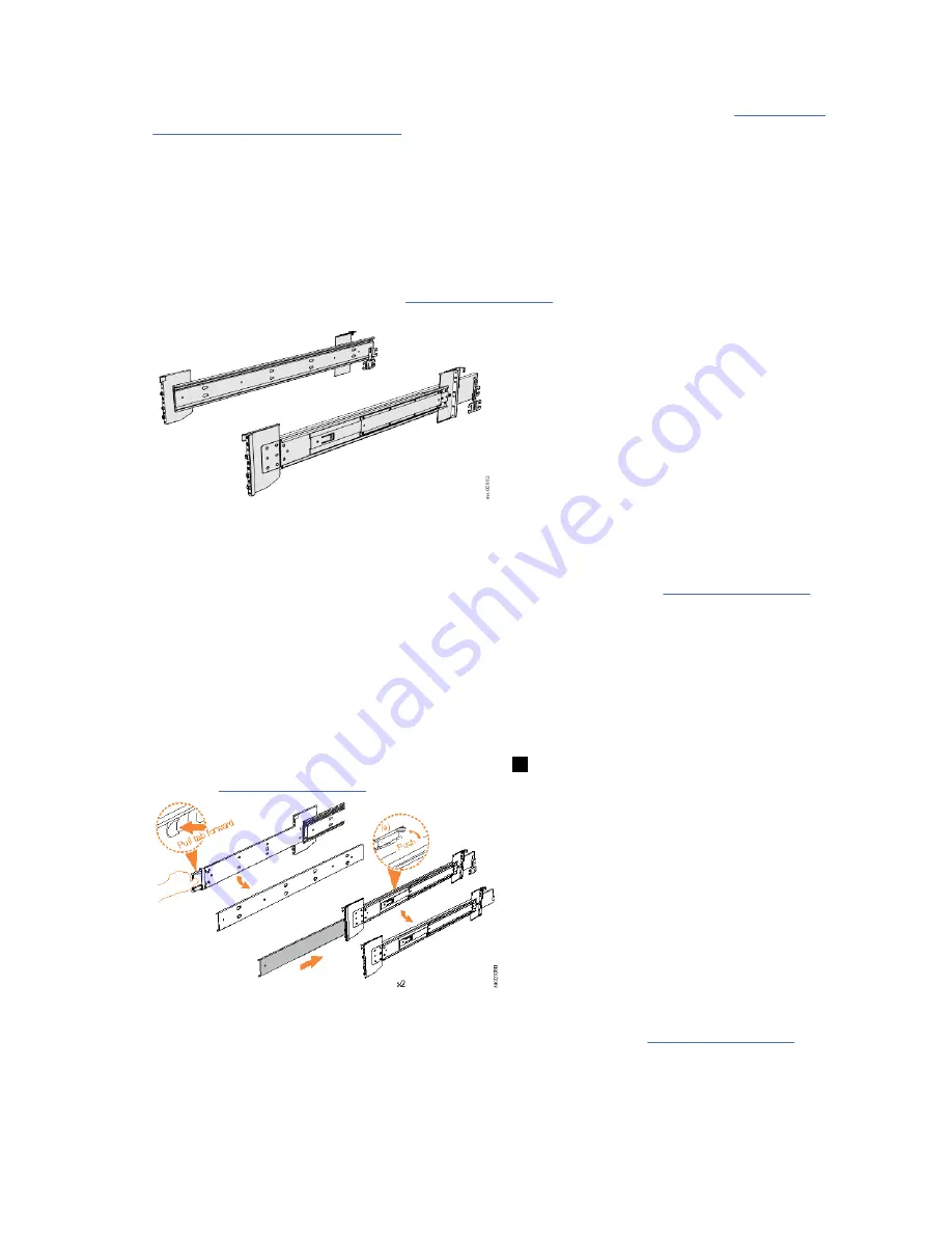
1. Locate the hardware that is used to install the rails, including the M4xL6 and M5xL13 screws.

Set the hardware, which is shown in Figure 11 on page 22, aside for use later in the installation

process.

Figure 11. Support rails

2. Select an available 5U92 space in your rack to install the expansion enclosure.Refer to the rack

configuration planning worksheet that is completed by the customer, and select the 5U92 space for

the IBM Cloud Object Storage System

 5U92 disk enclosure, as shown in Figure 16 on page 23.

Important notes:
• When you select a rack location, ensure that the enclosure and its parts are easily accessible. Allow

enough space for the lid to be easily removed and for internal components, such as drives and

secondary expansion modules, to be serviced.

• When all components and drives are installed, the disk enclosure is heavy. Install the support rails

and enclosure at the lowest available position. Do not install the rails and enclosure above position

U25 in the rack.

3. Remove the inner member of the rail. Push the tab (

 a 

) and slide the middle rail member back, as

shown in Figure 12 on page 22.

Figure 12. Detaching the inner rail section

4. Use four M4 screws to attach the inner rail to the side of the enclosure. Figure 13 on page 23 shows

the screw locations.

22  IBM Cloud Object Storage System

 Version 3.15.6: J15 Appliance Manual

Summary of Contents for 5U92

Page 1: ...IBM Cloud Object Storage System Version 3 15 6 J15 Appliance Manual IBM...

Page 2: ...n to the nut shell on the controller Node and run the FW update command enclosure firmware upgrade 3 After firmware update is complete check FW version by running the command enclosure firmware versio...

Page 3: ...stalling the 5U92 disk enclosure 16 Identify the hardware components 19 Removing the top cover 21 Installing the support rails for an optional 5U92 disk enclosure 22 Installing or replacing the fascia...

Page 4: ...emoving a power supply 93 Removing the display panel assembly 95 Removing an expansion canister 98 Removing a fan module 99 Removing a fan interface board 101 Notices 105 Trademarks 106 Homologation s...

Page 5: ...disk enclosure cover 21 11 Support rails 22 12 Detaching the inner rail section 22 13 Screw locations to attach the inner rail to the enclosure 23 14 Attaching the inner rail section to the enclosure...

Page 6: ...of the components of the CMA assemblies 39 36 Left view of SAS port orientation on disk enclosures 40 37 Correct orientation for SAS cable connectors 40 38 Example of SAS cables routed through the cab...

Page 7: ...59 59 Display panel assembly 61 60 Installing the display panel assembly 62 61 Expansion canister 62 62 Install the expansion canister 63 63 Fan module orientation 64 64 Replace fan module 64 65 FIB p...

Page 8: ...secondary expander modules 85 85 Location of LEDs on the secondary expander module 86 86 Remove the secondary expander module 87 87 Secondary expander module connectors 87 88 Secondary expander module...

Page 9: ...release tab 100 100 Remove fan module 101 101 Fan module LED 102 102 Location of the FIB cover 102 103 Loosen the FIB screws 103 104 Remove the FIB from the chassis 103 105 FIB parts removed from the...

Page 10: ...x...

Page 11: ...closure with 92 SAS drives 14 5 Enclosure weight as FRUs are installed 14 6 Display panel LEDs 45 7 Power supply unit LEDs 46 8 LED indicators on drives 47 9 LED indicators on secondary expansion modu...

Page 12: ...xii...

Page 13: ...the name of your system in the Search field for example IBM Cloud Object Storage System c Click the documentation link Safety notices and labels Review the safety notices and safety information labels...

Page 14: ...f a hazard that has the potential of causing moderate or minor personal injury C001 2 After you download the IBM System Safety Notices document open it 3 Under the language find the matching identific...

Page 15: ...To avoid personal injury or equipment damage disconnect the attached power cords telecommunication systems networks and modems before you open the machine covers unless instructed otherwise in the in...

Page 16: ...ction before each use Do not over force moving or rolling the LIFT TOOL with stabilizer brake engaged Do not raise lower or slide platform load shelf unless stabilizer brake pedal jack is fully engage...

Page 17: ...for use to assist lift install remove units load up into rack elevations It is not to be used loaded transporting over major ramps nor as a replacement for such designated tools like pallet jacks wal...

Page 18: ...nding Always assure self that winch is holding load before releasing winch handle A winch accident could cause serious injury Not for moving humans Make certain clicking sound is heard as the equipmen...

Page 19: ...removable outriggers they must be reinstalled before the cabinet is relocated Inspect the route that you plan to take to eliminate potential hazards Verify that the route that you choose can support...

Page 20: ...tch on power to the machine until all possible unsafe conditions are corrected When performing a machine inspection Assume that an electrical safety hazard is present Perform all ontinuity grounding a...

Page 21: ...optional devices starting from the bottom of the rack cabinet Rack mounted devices are not to be used as shelves or work spaces Do not place objects on top of rack mounted devices Each rack cabinet m...

Page 22: ...n conductive material to allow for metal to metal contact All PROTECTIVE EARTHING CONDUCTORS should terminate at this main protective earthing terminal or at points marked with R010 Special caution an...

Page 23: ...lowing precautions Limit your movement Movement can cause static electricity to build up around you Handle the device carefully holding it by its edges or frame Do not touch solder joints pins or expo...

Page 24: ...xxiv IBM Cloud Object Storage System Version 3 15 6 J15 Appliance Manual...

Page 25: ...s G229 9054 The guide contains translated caution and danger statements Each caution and danger statement has a number that you can use to locate the corresponding statement in a specific language IBM...

Page 26: ...M websites for help services and information Website Address IBM home page http www ibm com Directory of worldwide contacts http www ibm com planetwide Support for products www ibm com support Support...

Page 27: ...re that they are connected Check all power switches to make sure that the system and optional devices are turned on Use the troubleshooting information in your system documentation The troubleshooting...

Page 28: ...or the Support Line Offering If you have questions about how to use and configure the machine sign up for the IBM Support Line offering to get a professional answer Support plans can be purchase on th...

Page 29: ...ces when lifting The fully populated enclosure weighs about 37 kg 82 lbs At least three people are required to lift and install the enclosure into the rack or to remove an enclosure from the rack CAUT...

Page 30: ...attempt to switch power to the machine until all possible unsafe conditions are corrected Before you open the device covers unless instructed otherwise in the installation and configuration procedure...

Page 31: ...hat are listed in the packing slip match what is in the box and that any optional items that you ordered are included in the list Your shipment might contain extra items depending on the order Note If...

Page 32: ...4 IBM Cloud Object Storage System Version 3 15 6 J15 Appliance Manual...

Page 33: ...nstall the fascia 7 Install the drives 8 Install the cable management arm 9 Connect the SAS disk enclosures to the system You will need the following items Three or more persons or a lifting device to...

Page 34: ...vices starting from the bottom of the rack cabinet Rack mounted devices are not to be used as shelves or work spaces Do not place objects on top of rack mounted devices Each rack cabinet might have mo...

Page 35: ...s and optional devices starting from the bottom of the rack cabinet Rack mounted devices are not to be used as shelves or work spaces Do not place objects on top of rack mounted devices Each rack cabi...

Page 36: ...ke to eliminate potential hazards Verify that the route that you choose can support the weight of the loaded rack cabinet Refer to the documentation that comes with your rack cabinet for the weight of...

Page 37: ...should be terminated at that point A recognized or certified closed loop connector ring terminal should be used and secured to the frame with a lock washer using a bolt or stud The connector should be...

Page 38: ...ction before each use Do not over force moving or rolling the LIFT TOOL with stabilizer brake engaged Do not raise lower or slide platform load shelf unless stabilizer brake pedal jack is fully engage...

Page 39: ...r use to assist lift install remove units load up into rack elevations It is not to be used loaded transporting over major ramps nor as a replacement for such designated tools like pallet jacks walkie...

Page 40: ...ch to unwind freely Freewheeling will cause uneven cable wrapping around winch drum damage cable and may cause serious injury C048 CAUTION If the System slide rails are installed above EIA location 29...

Page 41: ...sembly 0 020 0 044 1 0 020 0 044 PSU fascia 1U cover 0 010 0 022 1 0 010 0 022 Power supply unit PSU 3 335 7 352 2 6 670 14 705 Secondary expansion module 0 826 1 821 2 1 652 3 642 Fan module 0 890 1...

Page 42: ...drives are installed Table 4 Weight of an enclosure with 92 SAS drives FRU description Approximate weigh per unit Maximum supported Approximate extra weight kg lb kg lb 3 5 inch Near Line SAS hard dis...

Page 43: ...d 4U PSUs Expansion canisters Fan modules Fan interface board Display assembly Drives Cover 58 127 9 Note The following FRUs are installed when the enclosure is initially shipped Enclosure Secondary e...

Page 44: ...nical lift to support the weight of the disk enclosure Unpacking and installing the 5U92 disk enclosure Before you unpack and install the 5U92 disk enclosure ensure that you review and follow the inst...

Page 45: ...il kit 2 Cable management arm 3 Fascia Other parts such as the cover secondary expander modules and fans are installed in the enclosure However due to weight considerations you must remove some parts...

Page 46: ...cribed in step 1 on page 36 in Installing or replacing a 5U92 disk enclosure in a rack on page 29 11 Remove the 4U and 1U fascia from the boxes in which they were shipped as shown in Figure 3 on page...

Page 47: ...screws 3 Power supply unit indicators 4 Power supply units PSUs 5 PSU fascia 1U 6 Front fascia 4U However as Figure 5 on page 19 shows the 4U and 1U fascias are packaged separately You must attach th...

Page 48: ...SU 1 Support rails Figure 7 on page 20 shows the support rails for the disk enclosure The support rails are packaged separately from the disk enclosure Figure 7 Support rails Cable management arm The...

Page 49: ...osure or its components to shut down to protect from overheating Procedure 1 Use the slide rails to pull the enclosure out from the rack See Removing a 5U92 disk enclosure from a rack on page 69 for d...

Page 50: ...space for the IBM Cloud Object Storage System 5U92 disk enclosure as shown in Figure 16 on page 23 Important notes When you select a rack location ensure that the enclosure and its parts are easily ac...

Page 51: ...e 6 Use the M5 screws to install the outer rail member and bracket assembly to the rack as shown in Figure 15 on page 23 Figure 15 Installing the rail assembly to the rack frame For example Figure 16...

Page 52: ...ide rails to pull the enclosure out of the rack For more information see Removing a 5U92 disk enclosure from a rack on page 69 Attach the front 4U fascia 2 Align the front 4U fascia with the enclosure...

Page 53: ...cause the enclosure or its components to shut down to protect from overheating Ensure that the drive that you are replacing is not a spare or a member of an array The drive status is shown in Pools In...

Page 54: ...ure The drive slots are numbered 1 14 from left to right and A G from the back to the front of the enclosure Figure 20 Drive locations in a 5U92 disk enclosure The drive slots must be populated sequen...

Page 55: ...the bottom of the latch is aligned with the top of the partition Ensure that the handle is not open more than 45 degrees from the drive carrier 2 in Figure 23 on page 27 9 Rotate the handle down to l...

Page 56: ...own to protect from overheating About this task To install or replace the top cover on the 5U92 disk enclosure complete the following steps Procedure 1 Carefully lower the cover and ensure that it is...

Page 57: ...you begin DANGER Multiple power cords The product might be equipped with multiple AC power cords or multiple DC power cables To remove all hazardous voltages disconnect all power cords and power cable...

Page 58: ...not blocked or reduced on any side front or back of a unit used for air flow through the unit Consideration should be given to the connection of the equipment to the supply circuit so that overloading...

Page 59: ...vicing unless specified by the manufacturer Attempting to move the drawer partially or completely out of the rack might cause the rack to become unstable or cause the drawer to fall out of the rack R0...

Page 60: ...osed loop connector ring terminal should be used and secured to the frame with a lock washer using a bolt or stud The connector should be properly sized to be suitable for the bolt or stud the locking...

Page 61: ...izer brake function before each use Do not over force moving or rolling the LIFT TOOL with stabilizer brake engaged Do not raise lower or slide platform load shelf unless stabilizer brake pedal jack i...

Page 62: ...t lift install remove units load up into rack elevations It is not to be used loaded transporting over major ramps nor as a replacement for such designated tools like pallet jacks walkies fork trucks...

Page 63: ...allow winch to unwind freely Freewheeling will cause uneven cable wrapping around winch drum damage cable and may cause serious injury C048 CAUTION If the System slide rails are installed above EIA lo...

Page 64: ...ack to lock the rails in the extended position 1 in Figure 28 on page 36 Figure 28 Replacing the 5U92 enclosure in the rack 2 Ensure that the ball bearing retainer clicks into place inside the front o...

Page 65: ...n Figure 28 on page 36 to secure the enclosure in the rack 9 Reconnect power to the disk enclosure Installing or replacing the cable management arm Use these procedures to install the cable management...

Page 66: ...Install the inner connector of the upper CMA assembly 1 to the inner member of the left support rail 2 as shown in Figure 32 on page 38 Figure 32 Install the inner connector of the upper CMA to the in...

Page 67: ...er rail member 11 Support rail connector the lower CMA 12 Connector base on outer rail member 5 Install the inner connector of the lower CMA assembly 7 to the inner member of the right support rail 8...

Page 68: ...losure is installed in the rack the expansion canisters are upside down The input cables connect to both the left port port 1 and the left port port 2 on the expansion canister from the right side of...

Page 69: ...gement arms NOTE SAS cables are not installed on the left hand side of expansion canister for the IBM Cloud Object Storage 5U92 disk enclosure 9 When both ends of a SAS cable are correctly connected t...

Page 70: ...cluding the technician port The technician port is used for initial setup of the system by directly attaching to a personal computer It can also be used to complete service actions for the system USB...

Page 71: ...nectors on the rear of the expansion enclosure The enclosure automatically powers on and begins its Power On Self Tests POST 2 Secure the power cables in the cable retainer at each power connector on...

Page 72: ...nt display panel and each PSU 1 and 3 in Figure 41 on page 43 are also lit when the power is connected See 5U92 disk enclosure LEDs and indicators on page 45 for information about the status that is p...

Page 73: ...d for each of the power supply units 3 Figure 45 LEDs on the front of the disk enclosure 1 Display panel LEDs 2 Rack retention thumb screws 3 Power supply unit LEDs 4 Power supply units PSUs 5 PSU fas...

Page 74: ...C power outputs are within specification Off DC power is not available 3 Fault Amber On A fault is detected in the PSU Off No faults are detected LEDs inside of the disk enclosure Each of the drives a...

Page 75: ...icator Table 9 on page 47 describes the meaning of the LEDs on each secondary expansion module Table 9 LED indicators on secondary expansion modules Function Color Status Description 1 Power Green On...

Page 76: ...Color Status Description Activity for drives Power for secondary expansion modules Green On The drive is ready to be used The secondary expansion module is receiving power Flashing The drive is operat...

Page 77: ...em 5U92 disk enclosure LEDs on the rear of the enclosure provide information about each fan module each expansion canister and SAS links Figure 50 LEDs on the back of the disk enclosure The disk enclo...

Page 78: ...uct data VPD error occurred 3 Canister power Green Off Canister is off On Canister is receiving power 4 and 6 SAS link fault Amber Off No faults are detected All four phys have a link connection On Se...

Page 79: ...nstalling or replacing the top cover on page 28 5 Installing or replacing a drive on page 25 6 Replacing a disk enclosure on page 51 7 Installing or replacing the fascia on page 24 8 Installing or rep...

Page 80: ...page 98 Fan modules Removing a fan module on page 99 The expansion enclosure was removed from the rack as described in Removing a 5U92 disk enclosure from a rack on page 69 A suitably rated mechanica...

Page 81: ...nstalling or replacing an expansion canister on page 62 Installing or replacing a fan module on page 63 Installing or replacing the top cover on page 28 8 Reconnect the SAS cables as described in Remo...

Page 82: ...is 01LJ607 you can remove or replace the secondary expander module while the enclosure is powered on Important You can replace a secondary expander module without powering off the expansion enclosure...

Page 83: ...y expander module was removed as described in Removing a secondary expander module on page 84 Procedure 1 Slide the expansion enclosure out from the rack as described in Removing a 5U92 disk enclosure...

Page 84: ...he secondary expander module down into position in the enclosure 6 Rotate the handles on the secondary expander module to the closed position to lock it in the enclosure 7 If needed repeat step 3 on p...

Page 85: ...lace a PSU without powering off the expansion enclosure However to maintain operating temperature replace the PSU within 10 minutes of its removal When a PSU is removed the reduction in airflow throug...

Page 86: ...Preparing to install the power supply 3 Slide the PSU forward into the chassis until it clicks in to place as shown in Figure 57 on page 59 58 IBM Cloud Object Storage System Version 3 15 6 J15 Applia...

Page 87: ...on the PSU and ensure the handle lock clicks in to place 5 Verify that the AC input and the DC power indicators are lit on the front of the PSU as shown in Figure 58 on page 59 Figure 58 Power supply...

Page 88: ...e met The expansion enclosure was moved out from the rack on the slide rails as described in Removing a 5U92 disk enclosure from a rack on page 69 The top cover was removed as described in Removing th...

Page 89: ...ay panel assembly in the slot at the front of the expansion enclosure as shown in Figure 60 on page 62 Ensure the display panel assembly which is shown in Figure 59 on page 61 faces toward the outside...

Page 90: ...re replace the expansion canister within 10 minutes of its removal When an expansion canister is removed the reduction in airflow through the enclosure might cause the enclosure or its components to s...

Page 91: ...rm to the inner member of the slide rail Installing or replacing a fan module You can reinstall a fan module or replace a faulty fan module in a 5U expansion enclosure Before you begin Important You c...

Page 92: ...ng all fan modules 3 Repeat steps 1 on page 64 and 2 on page 64 for each fan module to be replaced 4 Power on the expansion enclosure Installing or replacing a fan interface board You can replace a fa...

Page 93: ...1 and 2 to the drive board FIB 2 connects fan modules 3 and 4 If the fault LED on each fan module is lit it is possible that the FIB that controls those modules needs to be replaced You can also issue...

Page 94: ...he retaining screws that secure the FIB to the drive board as shown in Figure 67 on page 66 Figure 67 Secure the FIB to the drive board 4 If needed repeat steps 2 on page 65 and 3 on page 66 to replac...

Page 95: ...Installing or replacing the top cover on page 28 10 Reconnect power to the enclosure as described in Powering on the 5U92 disk enclosure on page 42 Procedures Removing 5U92 disk enclosure parts You ca...

Page 96: ...Figure 69 on page 68 Figure 69 Remove the rail assembly from the front frame bracket 2 Remove the rail section by pulling it away from the front bracket as shown in Figure 69 on page 68 3 Remove the...

Page 97: ...zardous conditions due to uneven mechanical loading always install the heaviest devices in the bottom of the rack cabinet Always install servers and optional devices starting from the bottom of the ra...

Page 98: ...devices starting from the bottom of the rack cabinet Rack mounted devices are not to be used as shelves or work spaces Do not place objects on top of rack mounted devices Each rack cabinet might have...

Page 99: ...ou plan to take to eliminate potential hazards Verify that the route that you choose can support the weight of the loaded rack cabinet Refer to the documentation that comes with your rack cabinet for...

Page 100: ...er using a bolt or stud The connector should be properly sized to be suitable for the bolt or stud the locking washer the rating for the conducting wire used and the considered rating of the breaker T...

Page 101: ...zer brake function before each use Do not over force moving or rolling the LIFT TOOL with stabilizer brake engaged Do not raise lower or slide platform load shelf unless stabilizer brake pedal jack is...

Page 102: ...t lift install remove units load up into rack elevations It is not to be used loaded transporting over major ramps nor as a replacement for such designated tools like pallet jacks walkies fork trucks...

Page 103: ...old handle when lowering unwinding Always assure self that winch is holding load before releasing winch handle A winch accident could cause serious injury Not for moving humans Make certain clicking s...

Page 104: ...er mechanism 3 in Figure 71 on page 76 5 Slide the enclosure and inner rail member out of the rack 4 in Figure 71 on page 76 For safety ensure that a mechanical lift or other mechanism is available to...

Page 105: ...sure individually Figure 72 Upper and lower cable management arms To complete many service tasks you can swing the CMA assemblies away from the expansion enclosure You do not have to completely remove...

Page 106: ...er CMA assembly 3 in Figure 73 on page 78 4 Remove the outer connector from the inner member of the left support rail 4 in Figure 73 on page 78 5 Remove the inner connector of the upper CMA assembly 1...

Page 107: ...ember of the right support rail 8 as shown in Figure 74 on page 79 Replace the CMA assembly 9 To reinstall the CMA or replace it with one from FRU stock follow the procedure in Installing or replacing...

Page 108: ...rom the rear of the enclosure so that the expansion canister is accessible Figure 76 Lower CMA assembly moved Procedure 1 To release the upper CMA push the latch on the support rail connector 5 to rel...

Page 109: ...ome service tasks you might need to remove the top cover from a 5U92 disk enclosure Before you begin Important You can remove the cover without powering off the disk enclosure However to maintain oper...

Page 110: ...ternal Storage in the management GUI If the drive is a member of an array follow the fix procedures in the management GUI The fix procedures minimize the risk of losing data or access to data the proc...

Page 111: ...3 Do not replace a drive unless the drive fault indicator is on or you are instructed to do so by a fix procedure When lit the green indicator shows that activity is occurring on the drive A label on...

Page 112: ...through step 7 on page 84 for each drive you need to remove Replace the drive 9 To reinstall a drive or replace it with one from FRU stock follow the procedure in Installing or replacing a drive on pa...

Page 113: ...hut down to protect from overheating About this task The secondary expander modules provide SAS connectivity between the expansion canisters and the drives Each drive has 2 SAS ports SAS port 1 of eac...

Page 114: ...assumes that the following conditions were met The expansion enclosure is slid out from the rack as described in Removing a 5U92 disk enclosure from a rack on page 69 The top cover was removed as des...

Page 115: ...dary expander module do not touch the connectors inside the enclosure FRU P N 01LJ112 which are shown in Figure 87 on page 87 Figure 87 Secondary expander module connectors 5 Place the secondary expan...

Page 116: ...5U expansion enclosure with a new one from FRU stock Before you begin DANGER Multiple power cords The product might be equipped with multiple AC power cords or multiple DC power cables To remove all h...

Page 117: ...interconnect board and internal power cables If a fault with the drive board or the intercanister link is suspected you can replace the enclosure However you can remove the parts from the old expansio...

Page 118: ...10 Firmware FW on an enclosure must be updated and to do this attach a single SAS cable between the rightmost SAS port on the rear of the controller and port 1 on the right hand ESM of the Disk Enclo...

Page 119: ...power supply units PSUs As Figure 89 on page 91 shows the fascias are independent you can remove or replace one without having to remove or replace the other Figure 89 Fascia components on the expans...

Page 120: ...the chassis as shown in Figure 90 on page 92 The PSU fascia disengages from the slot and pin that connect it to each side of the chassis You must remove the bottom fascia to access and service either...

Page 121: ...hat you perform the following tasks Do not remove a faulty PSU until its replacement is ready to be installed Do not remove a PSU from an operational enclosure for more than approximately 10 minutes T...

Page 122: ...dle lock to release the handles on the PSU 4 Rotate the handles outward as shown in Figure 92 on page 94 Figure 92 Releasing the power supply handles 5 Carefully pull the PSU out of the expansion encl...

Page 123: ...lling or replacing a power supply on page 57 Removing the display panel assembly You can remove the display panel assembly from a 5U expansion enclosure Procedure 1 Slide the expansion enclosure out o...

Page 124: ...Removing the display panel assembly 4 Carefully pull the display panel assembly which is shown in Figure 95 on page 97 out of the chassis 96 IBM Cloud Object Storage System Version 3 15 6 J15 Applian...

Page 125: ...e the display panel assembly 5 To reinstall the display panel assembly or replace it with one from FRU stock follow the procedure in Installing or replacing the display panel assembly on page 60 Chapt...

Page 126: ...ure and control enclosure system If either of the two expansion canisters has a failure the other expansion canister assumes the full I O load Figure 96 on page 98 shows the features of an expansion e...

Page 127: ...ver to maintain operating temperature do not remove more than one fan module at a time Remove a faulty fan module only when its replacement is ready to be installed Do not remove a fan module from an...

Page 128: ...fan modules 2 Press the release tab on the fan module as Figure 99 on page 100 shows Figure 99 Fan module release tab 3 Use the handle to pull the fan module out of the expansion enclosure chassis as...

Page 129: ...moved from the rack as described in Removing a 5U92 disk enclosure from a rack on page 69 Ensure that you use a lift to support the weight of the enclosure About this task The 5U expansion enclosure c...

Page 130: ...igure 102 on page 102 The screws are on each side of the chassis Place the cover and cover screws in a safe location Figure 102 Location of the FIB cover 2 Use a cross head screwdriver to loosen the r...

Page 131: ...e to pull the FIB out of the expansion enclosure chassis as shown in Figure 104 on page 103 Figure 104 Remove the FIB from the chassis 4 Place the FIB shown in Figure 105 on page 104 in a safe locatio...

Page 132: ...on page 103 to remove the other FIB Replace the fan interface board 6 To reinstall a fan interface board or replace it with one from FRU stock follow the procedure in Installing or replacing a fan int...

Page 133: ...Japan Ltd 19 21 Nihonbashi Hakozakicho Chuo ku Tokyo 103 8510 Japan INTERNATIONAL BUSINESS MACHINES CORPORATION PROVIDES THIS PUBLICATION AS IS WITHOUT WARRANTY OF ANY KIND EITHER EXPRESS OR IMPLIED I...

Page 134: ...names and addresses used by an actual business enterprise is entirely coincidental COPYRIGHT LICENSE This information contains sample application programs in source language which illustrate programm...

Page 135: ...nt this equipment may cause radio interference Germany Notice Deutschsprachiger EU Hinweis Hinweis f r Ger te der Klasse A EU Richtlinie zur Elektromagnetischen Vertr glichkeit Dieses Produkt entspric...

Page 136: ...Germany Tel 49 800 225 5426 e mail Halloibm de ibm com Generelle Informationen Das Ger t erf llt die Schutzanforderungen nach EN 55024 und EN 55032 Klasse A Japan Electronics and Information Technolog...

Page 137: ...ated in a commercial environment This equipment generates uses and can radiate radio frequency energy and if not installed and used in accordance with the instruction manual may cause harmful interfer...

Page 138: ...ation is subject to the following two conditions 1 this device might not cause harmful interference and 2 this device must accept any interference received including interference that might cause unde...

Page 139: ...Index C comments xxvi F feedback xxvi R reader feedback xxvi S send a comment xxvi T trademarks 106 Index 111...

Page 140: ...112 IBM Cloud Object Storage System Version 3 15 6 J15 Appliance Manual...

Page 141: ......

Page 142: ...IBM Part Number 02YC410 1P P N 02YC410...

Reviews: