background image

Taiwan Notice

United States Federal Communications Commission (FCC) Notice
This equipment has been tested and found to comply with the limits for a Class B digital device, pursuant

to Part 15 of the FCC Rules. These limits are designed to provide reasonable protection against harmful

interference in a residential installation. This equipment generates, uses, and can radiate radio frequency

energy and, if not installed and used in accordance with the instructions, may cause harmful interference

to radio communications. However, there is no guarantee that interference will not occur in a particular

installation. If this equipment does cause harmful interference to radio or television reception, which can

be determined by turning the equipment off and on, the user is encouraged to try to correct the

interference by one or more of the following measures:
• Reorient or relocate the receiving antenna.
• Increase the separation between the equipment and receiver.
• Connect the equipment into an outlet on a circuit different from that to which the receiver is connected.
• Consult an IBM-authorized dealer or service representative for help.
Properly shielded and grounded cables and connectors must be used in order to meet FCC emission

limits. Proper cables and connectors are available from IBM-authorized dealers. IBM is not responsible

for any radio or television interference caused by using other than recommended cables and connectors

or by unauthorized changes or modifications to this equipment. Unauthorized changes or modifications

could void the user's authority to operate the equipment.
This device complies with Part 15 of the FCC rules. Operation is subject to the following two conditions:

(1) this device may not cause harmful interference, and (2) this device must accept any interference 

received, including interference that may cause undesired operation. 

Responsible Party:

International Business Machines Corporation

New Orchard Road 

Armonk, New York 10504 

Contact for FCC compliance information only: [email protected]

Terms and conditions

Permissions for the use of these publications are granted subject to the following terms and conditions.
Applicability: These terms and conditions are in addition to any terms of use for the IBM website.
Personal Use: You may reproduce these publications for your personal, noncommercial use provided that

all proprietary notices are preserved. You may not distribute, display or make derivative works of these

publications, or any portion thereof, without the express consent of IBM.
Commercial Use: You may reproduce, distribute and display these publications solely within your

enterprise provided that all proprietary notices are preserved. You may not make derivative works of

these publications, or reproduce, distribute or display these publications or any portion thereof outside

your enterprise, without the express consent of IBM.

Notices  75

Summary of Contents for 5887

Page 1: ...Power Systems Installing the 5887 disk drive enclosure IBM GI11 9909 03...

Page 2: ...G229 9054 and the IBM Environmental Notices and User Guide Z125 5823 This edition applies to IBM Power Systems servers that contain the POWER9 processor and to all associated models Copyright Interna...

Page 3: ...s and installing covers 33 Completing the 5887 disk drive enclosure installation 35 Reference information 37 Stopping a system 37 Stopping a system that is not managed by an HMC 37 Stopping a system b...

Page 4: ...iv...

Page 5: ...00 300 8751 German safety information Das Produkt ist nicht f r den Einsatz an Bildschirmarbeitspl tzen im Sinne 2 der Bildschirmarbeitsverordnung geeignet Laser safety information IBM servers can use...

Page 6: ...t 1 Turn off everything unless instructed otherwise 2 For AC power remove the power cords from the outlets 3 For racks with a DC power distribution panel PDP turn off the circuit breakers located in t...

Page 7: ...n a different rack cabinet An electrical outlet that is not correctly wired could place hazardous voltage on the metal parts of the system or the devices that attach to the system It is the responsibi...

Page 8: ...cabinet is relocated Inspect the route that you plan to take to eliminate potential hazards Verify that the route that you choose can support the weight of the loaded rack cabinet Refer to the docume...

Page 9: ...position for example when working from a ladder Stability hazard The rack may tip over causing serious personal injury Before extending the rack to the installation position read the installation ins...

Page 10: ...be equipped with multiple AC power cords or multiple DC power cables To remove all hazardous voltages disconnect all power cords and power cables L003 L007 CAUTION A hot surface nearby L007 x Power S...

Page 11: ...ing into the other end of a disconnected optical fiber to verify the continuity of optic fibers may not injure the eye this procedure is potentially dangerous Therefore verifying the continuity of opt...

Page 12: ...ooth platforms without appreciable force so take care not to push or lean Keep riser tilt adjustable angling platform option flat at all times except for final minor angle adjustment when needed Do no...

Page 13: ...itable for connection to intrabuilding or unexposed wiring or cabling only The intrabuilding ports of this equipment must not be metallically connected to the interfaces that connect to the OSP outsid...

Page 14: ...xiv Power Systems Installing the 5887 disk drive enclosure...

Page 15: ...ons see the Power Systems Prerequisites website https www14 software ibm com support customercare iprt home 3 Choose from the following options If your 5887 disk drive enclosure arrived to your site p...

Page 16: ...g the following steps a Find the slotted opening in the small front bracket A below the left enclosure services manager ESM and loosen the power supply cord B that is visible in the opening b Carefull...

Page 17: ...ng the small front brackets b Using a screwdriver remove the screw that attaches the large bracket to the left flange of the rack frame Then remove the screw that attaches the bracket to right flange...

Page 18: ...acket toward the rear of the rack Lift the bracket with two hands to remove it from the side rails Tip Save all of the brackets that you remove for future reinstallation and for shipping of the enclos...

Page 19: ...ock and secure the ESM units by completing the following steps a Moving one ESM at a time slide the unit approximately 75 mm 3 in toward the chassis b For one ESM at a time place your forefingers unde...

Page 20: ...Figure 5 Opening the ESM release levers c Moving one ESM at a time slide the unit into the chassis until it stops 6 Power Systems Installing the 5887 disk drive enclosure...

Page 21: ...r fully closed and latched position Figure 7 Closing the ESM release levers 10 Dock and secure the power supplies by completing the following steps a Moving one power supply at a time slide the unit a...

Page 22: ...time rest your right thumb on the terracotta release latch beside the unit handle and your fingertips on the handle In one motion squeeze the release latch to the right and swing the handle down into...

Page 23: ...g the power supply release handle c Moving one power supply at a time slide the unit into the chassis until it stops Installing the 5887 disk drive enclosure or setting up a preinstalled 5887 disk dri...

Page 24: ...10 Docking the power supplies d Moving one power supply at a time swing the unit handle up and into its fully closed position on the release latch 10 Power Systems Installing the 5887 disk drive encl...

Page 25: ...ing the 5887 disk drive enclosure to your system on page 23 Completing inventory for the 5887 disk drive enclosure Learn how to complete inventory for the 5887 disk drive enclosure About this task Pro...

Page 26: ...rack complete the following steps Procedure 1 Determine where in the rack to place the enclosure in relation to other system hardware As you plan for installing the enclosure in a rack keep in mind th...

Page 27: ...be used for the enclosure b Use tape a marker or a pencil to mark the top mounting hole A of the lowest EIA unit Note Mark the rack so that these marks can also be seen from the rear of the rack c Cou...

Page 28: ...and fittings for your rack If your rack has square support flange holes or screw thread support flange holes ensure that the rails and fittings match the support flange holes that are used on your ra...

Page 29: ...Figure 14 Installing the spring to the rail 4 Open the hinge bracket on each end of the rail Installing the 5887 disk drive enclosure or setting up a preinstalled 5887 disk drive enclosure 15...

Page 30: ...ter of the open space inside the rack The enclosure stop B is located toward the rear of the rack 6 Locate the two marks that were made previously on the Electronic Industries Alliances EIA strips 7 A...

Page 31: ...e rail on the rack 8 At the front of the rail close the front hinge bracket to secure the rail to the rack cabinet flange Installing the 5887 disk drive enclosure or setting up a preinstalled 5887 dis...

Page 32: ...pen hole in the bracket between the two alignment pins at the rear of the rack 13 Repeat steps 6 on page 16 12 on page 18 for the other rail Installing the 5887 disk drive enclosure into the rack Lear...

Page 33: ...er B to show the mounting brackets 3 Pinch the release to rotate the cover up and off from the chassis flange as shown in Figure 18 on page 19 Figure 18 Removing the side covers 4 Using two people lif...

Page 34: ...9 Sliding the enclosure into the rack 6 Secure the front of the enclosure to the rack flanges with one M5 screw C in the top open hole in each bracket 20 Power Systems Installing the 5887 disk drive e...

Page 35: ...ostatic discharge ESD wrist strap on and that the ESD clip is plugged into a ground jack or connected to an unpainted metal surface If not do so now 2 Remove the drive from the static protective packa...

Page 36: ...ves are installed 7 Review the following information that is related to connecting this device The SAS disk drive enclosure can hold up to 24 drives The enclosure can be split logically into one two o...

Page 37: ...your enclosure when the system powered is turned on and when logical partitions are active if you have one of the following configurations Your system is managed by an IBM Hardware Management Console...

Page 38: ...g for serial attached SCSI cables http www ibm com support knowledgecenter POWER9 p9had p9had_sascabling htm A mode 1 connection of one 5887 disk drive enclosure by using a YO cable to a single SAS ad...

Page 39: ...2 on page 25 11 To unconfigure the SAS adapters complete these steps a Unconfigure the SAS adapters b Ensure that you have the electrostatic discharge ESD wrist strap on and that the ESD clip is plugg...

Page 40: ...one 5887 disk drive enclosure by using X cables to two SAS adapter pairs go to step 19 on page 30 To complete a mode 4 connection of one 5887 disk drive enclosure by using X cables to four independen...

Page 41: ...pair C as shown in Figure 25 on page 28 and then continue with Connecting cables power cords and installing covers on page 33 Note The single SAS adapter E has access to all 48 drive bays Notes Each...

Page 42: ...29 and then continue with Connecting cables power cords and installing covers on page 33 Notes Each adapter in the SAS adapter pair E has access to the other adapter and to all 48 drive bays If 6 Gb S...

Page 43: ...7 on page 30 and then continue with Connecting cables power cords and installing covers on page 33 Notes Independent SAS adapter 1 C does not have access to the other independent adapter and has acces...

Page 44: ...er cords and installing covers on page 33 Notes Each adapter in the SAS adapter pair 1 C has access to the other adapter and to drive bays D1 D12 Each adapter in the SAS adapter pair 2 D has access to...

Page 45: ...dent adapter and has access only to drive bays D1 D6 The cable that plugs into independent SAS adapter 2 D contains a label with the P2 identifier G This adapter does not have access to any other inde...

Page 46: ...Figure 29 Mode 4 connection of one 5887 disk drive enclosure by using X cables to four independent SAS adapters 32 Power Systems Installing the 5887 disk drive enclosure...

Page 47: ...ge ESD wrist strap on and that the ESD clip is plugged into a ground jack or connected to an unpainted metal surface If not do so now 2 If your installation requirements included the removal of the SA...

Page 48: ...ting the power cords 5 Reinstall the left cover A which contains the service indicators and the right cover B a Fit the slot on the top of the cover over the tab on the chassis flange b Rotate the cov...

Page 49: ...ur operating system by referring to the following information To configure a disk drive or SSD for use by AIX see Configuring a disk drive or solid state drive for use in an AIX system or AIX logical...

Page 50: ...ng the installed part www ibm com support knowledgecenter POWER9 p9haj pxhaj_hsmverify htm 3 You have completed the steps to install a 5887 disk drive enclosure If you were directed here from another...

Page 51: ...sure that all clients are shut down or that the clients have access to their devices by using an alternative method Stopping a system by using the control panel You might need to stop the system to co...

Page 52: ...host partition as a user with the authority to run the shutdown or pwrdwnsys Power Down System command 2 On the command line enter one of the following commands If your system is running the AIX oper...

Page 53: ...a Virtual I O Server VIOS logical partition ensure that all clients are shut down or that the clients have access to their devices by using an alternative method To power off a managed system you must...

Page 54: ...f necessary 2 Before you press the power button on the control panel ensure that power is connected to the system unit as follows All system power cables are connected to a power source The power LED...

Page 55: ...ions do not automatically start Continue with step 4 on page 41 4 Wait for the system to power on 5 In the navigation area click Power Restart Control Power On Off System The system power setting is d...

Page 56: ...ion unit connectors Learn about connector locations for enclosures and expansion units Connector locations for the 5887 disk drive enclosure Learn about connector locations for the 5887 disk drive enc...

Page 57: ...ort knowledgecenter POWER9 p9ecs p9ecs_emx0_loccodes htm For more information about the server locations see Part locations and location codes http www ibm com support knowledgecenter POWER9 p9ecs p9e...

Page 58: ...om support knowledgecenter POWER9 p9ecs p9ecs_locations htm Connector locations for POWER9 servers Learn about connector locations for POWER9 servers Connector locations for the 5105 22E 9008 22L 9009...

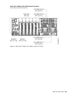
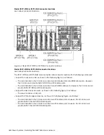
Page 59: ...G 9223 42H and 9223 42S systems Learn about connector locations for the 9009 41A 9009 41G 9009 42A 9009 42G 9223 42H and 9223 42S systems Figure 40 Connector locations for 9009 41A 9009 41G 9009 42A 9...

Page 60: ...trolling the internal SAS disk drive bays and have limited availability for attaching a 5887 disk drive enclosure or an ESLL or ESLS storage enclosure For more information about FC EJ0K see PCIe3 RAID...

Page 61: ...ot fanout module in your EMX0 PCIe Gen3 I O expansion drawer Table 3 PCIe3 cable adapter slots and priorities Feature code Description Slot priorities for two processors Slot priorities for three proc...

Page 62: ...cable adapter slots and priorities Feature code Description Slot priorities Node max EJ07 PCIe3 cable adapter for the PCIe3 expansion drawer FC EJ07 CCIN 6B52 Adapter part number 00TK704 1 7 3 5 2 8...

Page 63: ...ions for the 8286 41A system Learn about connector locations for the 8286 41A rack mounted and stand alone models The 8286 41A server provides cable connector locations via a SAS port for disk drive e...

Page 64: ...for the 8247 42L and 8286 42A systems Learn about connector locations for the 8247 42L and 8286 42A rack mounted models The 8247 42L and 8286 42A expanded function servers provide cable connector loca...

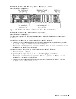
Page 65: ...408 44E and 8408 E8E systems Learn about connector locations for the 8408 44E and 8408 E8E systems The 8408 44E and 8408 E8E systems provide cable connector locations via a SAS port P1 C5 T3 for disk...

Page 66: ...E systems Learn about connector locations for the 9080 MHE 9080 MME 9119 MHE and 9119 MME systems The 9080 MHE 9080 MME 9119 MHE and 9119 MME servers provide cable connector locations via a SAS port f...

Page 67: ...Figure 48 Connector locations for the 9080 MHE 9080 MME 9119 MHE and 9119 MME systems Reference information 53...

Page 68: ...locations for POWER7 servers Model 8202 E4B connector locations Learn about connector locations on rack mounted and stand alone models Figure 49 Model 8202 E4B connector locations on a rack mounted mo...

Page 69: ...C1 slot can contain two 12X double data rate DDR cable ports However the C1 slot cannot provide both 12X DDR and PCIe cable ports The server contains a serial attached SCSI SAS port Support for disk d...

Page 70: ...ive enclosures and PCIe storage enclosures Model 8205 E6B connector locations Learn about connector locations on rack mounted and stand alone models Figure 52 Model 8205 E6B connector locations on a r...

Page 71: ...DR and PCIe cable ports The card installed in the C8 slot can contain two 12X DDR cable ports However the C8 slot cannot provide both 12X DDR and PCIe cable ports The port card type installed in the C...

Page 72: ...tor locations Learn about connector locations The 8231 E1C 8231 E1D or 8268 E1D server provides cable connector locations for the following enclosures Support for disk drive enclosures as shown in the...

Page 73: ...cations for the following enclosures Support for expansion units as shown in the following figure is as follows The C1 slot must contain the system power control network SPCN card and the C8 slot must...

Page 74: ...ble ports and 12X DDR cable ports at the same time The server contains a SAS port Figure 58 Model 8231 E2C or 8231 E2D connections for PCIe storage enclosures Model 8233 E8B connector locations Learn...

Page 75: ...R cable ports However the C2 slot cannot provide both 12X DDR and PCIe cable ports The card installed in the C3 slot can contain two 12X DDR cable ports However the C3 slot cannot provide both 12X DDR...

Page 76: ...Figure 61 Model 8248 L4T 8408 E8D or 9109 RMD connector locations for expansion units disk drive enclosures and PCIe storage enclosures 62 Power Systems Installing the 5887 disk drive enclosure...

Page 77: ...Model 9117 MMB or 9179 MHB connector locations Learn about connector locations Figure 62 Model 9117 MMB or 9179 MHB connector locations Reference information 63...

Page 78: ...ovide both 12X DDR and PCIe cable ports The card installed in the C3 slot can contain two 12X DDR cable ports However the C3 slot cannot provide both 12X DDR and PCIe cable ports Support for disk driv...

Page 79: ...Figure 64 Model 9117 MMD or 9179 MHD connector locations for expansion units disk drive enclosures and PCIe storage enclosures Reference information 65...

Page 80: ...66 Power Systems Installing the 5887 disk drive enclosure...

Page 81: ...ct s and or the program s described in this publication at any time without notice Any references in this information to non IBM websites are provided for convenience only and do not in any manner ser...

Page 82: ...se information technology content successfully Overview The IBM Power Systems servers include the following major accessibility features Keyboard only operation Operations that use a screen reader The...

Page 83: ...his Software Offering does not use cookies or other technologies to collect personally identifiable information If the configurations deployed for this Software Offering provide you as the customer th...

Page 84: ...nd die Ger te wie in den Handb chern beschrieben zu installieren und zu betreiben Des Weiteren d rfen auch nur von der IBM empfohlene Kabel angeschlossen werden IBM bernimmt keine Verantwortung f r di...

Page 85: ...tronics and Information Technology Industries Association JEITA Notice This statement applies to products less than or equal to 20 A per phase This statement applies to products greater than 20 A sing...

Page 86: ...use harmful interference in which case the user will be required to correct the interference at his own expense Properly shielded and grounded cables and connectors must be used in order to meet FCC e...

Page 87: ...tromagnetische Vertr glichkeit in den EU Mitgliedsstaatenund h lt die Grenzwerte der EN 55022 EN 55032 Klasse B ein Um dieses sicherzustellen sind die Ger te wie in den Handb chern beschrieben zu inst...

Page 88: ...on Technology Industries Association JEITA Notice This statement applies to products less than or equal to 20 A per phase This statement applies to products greater than 20 A single phase This stateme...

Page 89: ...or television interference caused by using other than recommended cables and connectors or by unauthorized changes or modifications to this equipment Unauthorized changes or modifications could void...

Page 90: ...determined by IBM the above instructions are not being properly followed You may not download export or re export this information except in full compliance with all applicable laws and regulations in...

Page 91: ......

Page 92: ...IBM Part Number 01LK649 GI11 9909 03 1P P N 01LK649...

Reviews: