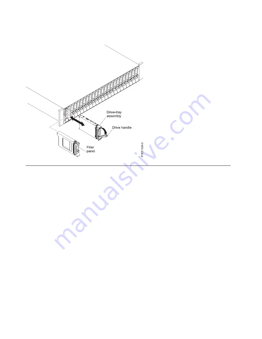
2.
Slide the disk drive into the disk drive enclosure until the drive stops.
3.
Rotate the handle to the locked position.
Removing and installing an enclosure services manager
You can remove and install an enclosure services manager (ESM) concurrently only when its amber fault
light is on solid.
Attention:
Failure to follow the steps sequentially for this field replaceable unit (FRU) removal or
installation might result in damage to the FRU or system.
Use the following precautions whenever you handle electronic components or cables:
v
Attach a wrist strap to an unpainted metal surface of your hardware to prevent electrostatic discharge
(ESD) from damaging your hardware.
v
If you do not have a wrist strap, before removing the product from ESD packaging and installing or
replacing hardware, touch an unpainted metal surface of the system for a minimum of 5 seconds.
v
Keep all electronic components in the shipping container or envelope until you are ready to install
them.
v
If you remove and reinstall an electronic component, temporarily place the component on an ESD pad
or blanket, if available.
v
During nonconcurrent replacement, do not combine the replacement of any ESM with the replacement
of the midplane unless there has been a power cycle of the disk drive enclosure with one new FRU at
a time. If multiple FRUs are replaced at the same time, the serial number is not preserved.
To remove and install an ESM, complete the following steps:
1.
Determine whether the repair can continue concurrently. To continue the repair concurrently, the
following conditions must be true:
v
A second ESM must already be installed.
v
The amber fault light of the failing ESM must be solid on.
Figure 2. Installing a disk drive in the disk drive enclosure
4
Summary of Contents for 5887
Page 1: ...Power Systems 5887 removal and replacement procedures IBM...
Page 2: ......
Page 3: ...Power Systems 5887 removal and replacement procedures IBM...
Page 6: ...iv...
Page 32: ...20...
Page 33: ......
Page 34: ...IBM Printed in USA...


