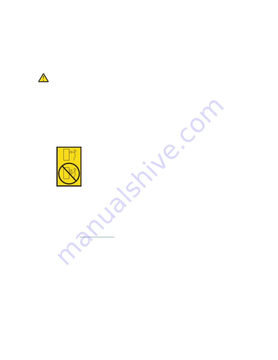
• Connect all devices installed in a rack cabinet to power devices installed in the same rack
cabinet. Do not plug a power cord from a device installed in one rack cabinet into a power device
installed in a different rack cabinet.
• An electrical outlet that is not correctly wired could place hazardous voltage on the metal parts
of the system or the devices that attach to the system. It is the responsibility of the customer to
ensure that the outlet is correctly wired and grounded to prevent an electrical shock. (R001 part
1 of 2)
(R001 part 2 of 2):
CAUTION:
• Do not install a unit in a rack where the internal rack ambient temperatures will exceed the
manufacturer's recommended ambient temperature for all your rack-mounted devices.
• Do not install a unit in a rack where the air flow is compromised. Ensure that air flow is not
blocked or reduced on any side, front, or back of a unit used for air flow through the unit.
• Consideration should be given to the connection of the equipment to the supply circuit so that
overloading of the circuits does not compromise the supply wiring or overcurrent protection. To
provide the correct power connection to a rack, refer to the rating labels located on the
equipment in the rack to determine the total power requirement of the supply circuit.
• (For sliding drawers.) Do not pull out or install any drawer or feature if the rack stabilizer brackets
are not attached to the rack or if the rack is not bolted to the floor. Do not pull out more than one
drawer at a time. The rack might become unstable if you pull out more than one drawer at a time.
• (For fixed drawers.) This drawer is a fixed drawer and must not be moved for servicing unless
specified by the manufacturer. Attempting to move the drawer partially or completely out of the
rack might cause the rack to become unstable or cause the drawer to fall out of the rack. (R001
part 2 of 2)
Procedure
1. If you are installing a new feature, ensure that you have the software that is required to support the
new feature. See IBM Prerequisite.
2. If you are installing or replacing something that might put your data at risk, ensure, wherever possible,
that you have a current backup of your system or logical partition (including operating systems,
licensed programs, and data).
3. Review the installation or replacement procedure for the feature or part.
4. Note the significance of color on your system.
Blue or terra-cotta on a part of the hardware indicates a touch point where you can grip the hardware
to remove it from or install it in the system, or open or close a latch. Terra-cotta might also indicate
that the part can be removed and replaced with the system or logical partition powered on.
5. Ensure that you have access to a medium flat-blade screwdriver, a Phillips screwdriver, and a pair of
scissors.
6. If parts are incorrect, missing, or visibly damaged, do the following steps:
• If you are replacing a part, contact the provider of your parts or next level of support.
• If you are installing a feature, contact one of the following service organizations:
– The provider of your parts or next level of support.
Common procedures for servicing or installing features in the 5104-22C, 9006-22C, or 9006-22P system 101
Summary of Contents for 5104-22C
Page 1: ...Power Systems Installing and configuring the IBM Power System LC922 9006 22P IBM ...
Page 14: ...xiv Power Systems Installing and configuring the IBM Power System LC922 9006 22P ...
Page 112: ...98 Power Systems Installing and configuring the IBM Power System LC922 9006 22P ...
Page 120: ...or or or 106 Power Systems Installing and configuring the IBM Power System LC922 9006 22P ...
Page 136: ...122 Power Systems Installing and configuring the IBM Power System LC922 9006 22P ...
Page 147: ......
Page 148: ...IBM ...


