background image

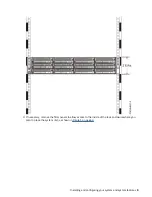
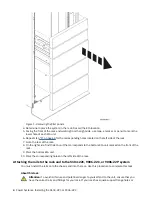
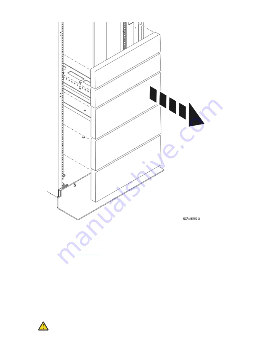
Figure 1. Removing the filler panels

4. Determine to place the system in the rack. Record the EIA location.
5. Facing the front of the rack and working from the right side, use tape, a marker, or pencil to mark the

lower hole of each EIA unit.

6. Repeat step “5” on page 4 for the corresponding holes located on the left side of the rack.
7. Go to the rear of the rack.
8. On the right side, find the EIA unit that corresponds to the bottom EIA unit marked on the front of the

rack.

9. Mark the bottom EIA unit.

10. Mark the corresponding holes on the left side of the rack.

Attaching the rails to the rack and to the 5104-22C, 9006-22C, or 9006-22P system

You must install the rails onto the chassis and into the rack. Use this procedure to complete this task.

About this task

Attention: To avoid rail failure and potential danger to yourself and to the unit, ensure that you

have the correct rails and fittings for your rack. If your rack has square support flange holes or

4  Power Systems: Installing the 5104-22C or 9006-22C

Summary of Contents for 5104-22C

Page 1: ...Power Systems Installing the 5104 22C or 9006 22C IBM...

Page 2: ...G229 9054 and the IBM Environmental Notices and User Guide Z125 5823 This edition applies to IBM Power Systems servers that contain the POWER9 processor and to all associated models Copyright Interna...

Page 3: ...nd marking the location in the rack for the system 2 Attaching the rails to the rack and to the system 4 Installing the system into the rack and connecting and routing power cables 7 Completing server...

Page 4: ...iv...

Page 5: ...00 300 8751 German safety information Das Produkt ist nicht f r den Einsatz an Bildschirmarbeitspl tzen im Sinne 2 der Bildschirmarbeitsverordnung geeignet Laser safety information IBM servers can use...

Page 6: ...isconnect 1 Turn off everything unless instructed otherwise 2 For AC power remove the power cords from the outlets 3 For racks with a DC power distribution panel PDP turn off the circuit breakers loca...

Page 7: ...devices that attach to the system It is the responsibility of the customer to ensure that the outlet is correctly wired and grounded to prevent an electrical shock R001 part 1 of 2 R001 part 2 of 2 CA...

Page 8: ...erify that the route that you choose can support the weight of the loaded rack cabinet Refer to the documentation that comes with your rack cabinet for the weight of a loaded rack cabinet Verify that...

Page 9: ...position for example when working from a ladder Stability hazard The rack may tip over causing serious personal injury Before extending the rack to the installation position read the installation ins...

Page 10: ...ght be equipped with multiple AC power cords or multiple DC power cables To remove all hazardous voltages disconnect all power cords and power cables L003 L007 CAUTION A hot surface nearby L007 x Powe...

Page 11: ...ing into the other end of a disconnected optical fiber to verify the continuity of optic fibers may not injure the eye this procedure is potentially dangerous Therefore verifying the continuity of opt...

Page 12: ...smooth platforms without appreciable force so take care not to push or lean Keep riser tilt adjustable angling platform option flat at all times except for final minor angle adjustment when needed Do...

Page 13: ...itable for connection to intrabuilding or unexposed wiring or cabling only The intrabuilding ports of this equipment must not be metallically connected to the interfaces that connect to the OSP outsid...

Page 14: ...xiv Power Systems Installing the 5104 22C or 9006 22C...

Page 15: ...version of this document is maintained online see Installing the IBM Power System http www ibm com support knowledgecenter POWER9 p9eip p9eip22c_install_kickoff htm To plan your server installation s...

Page 16: ...ort knowledgecenter POWER9 p9hbf p9hbf_racksafety htm 2 Determine where to place the system unit in the rack As you plan for installing the system unit in a rack consider the following information Org...

Page 17: ...ry remove the filler panels to allow access to the inside of the rack enclosure where you plan to place the system unit as shown in Figure 1 on page 4 Installing and configuring your system and system...

Page 18: ...orresponds to the bottom EIA unit marked on the front of the rack 9 Mark the bottom EIA unit 10 Mark the corresponding holes on the left side of the rack Attaching the rails to the rack and to the 510...

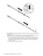
Page 19: ...ach the adapters to the rails The adapters slide and snap into place on the rail Note Each adapter is marked with either an A or a B For the left rail the A bracket should be in front and the B bracke...

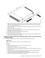
Page 20: ...em is also marked L or an R behind each handle a On the right side of the system align the metal tabs on the system chassis with the holes on the inner chassis slide rail A Slide the chassis slide rai...

Page 21: ...rough the EIA support flange Installing the 5104 22C 9006 22C or 9006 22P system into the rack and connecting and routing power cables After you install the system onto the rails in the rack connect a...

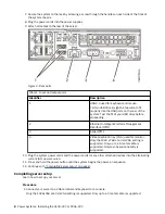
Page 22: ...I 3 Serial IPMI 4 Video Graphics Array VGA used for monitor Only the 1024 x 768 at 60 Hz VGA setting is supported Only up to a 3 meter cable is supported Only text based capability is supported 10 Plu...

Page 23: ...Firmware find your machine type and model and click Subscribe f Exit the Browse for a product screen g Click Delivery preferences to set email preferences and click Submit h Click Edit to select the t...

Page 24: ...10 Power Systems Installing the 5104 22C or 9006 22C...

Page 25: ...ct s and or the program s described in this publication at any time without notice Any references in this information to non IBM websites are provided for convenience only and do not in any manner ser...

Page 26: ...o use information technology content successfully Overview The IBM Power Systems servers include the following major accessibility features Keyboard only operation Operations that use a screen reader...

Page 27: ...provide you as the customer the ability to collect personally identifiable information from end users via cookies and other technologies you should seek your own legal advice about any laws applicable...

Page 28: ...rderungen der EU Richtlinie 2014 30 EU zur Angleichung der Rechtsvorschriften ber die elektromagnetische Vertr glichkeit in den EU Mitgliedsstaatenund h lt die Grenzwerte der EN 55022 EN 55032 Klasse...

Page 29: ...relle Informationen Das Ger t erf llt die Schutzanforderungen nach EN 55024 und EN 55022 EN 55032 Klasse A Japan Electronics and Information Technology Industries Association JEITA Notice This stateme...

Page 30: ...diate radio frequency energy and if not installed and used in accordance with the instruction manual may cause harmful interference to radio communications Operation of this equipment in a residential...

Page 31: ...luding the fitting of non IBM option cards German Notice Deutschsprachiger EU Hinweis Hinweis f r Ger te der Klasse B EU Richtlinie zur Elektromagnetischen Vertr glichkeit Dieses Produkt entspricht de...

Page 32: ...t die Schutzanforderungen nach EN 55024 und EN 55032 Klasse B Japan Electronics and Information Technology Industries Association JEITA Notice This statement applies to products less than or equal to...

Page 33: ...or television interference caused by using other than recommended cables and connectors or by unauthorized changes or modifications to this equipment Unauthorized changes or modifications could void...

Page 34: ...s determined by IBM the above instructions are not being properly followed You may not download export or re export this information except in full compliance with all applicable laws and regulations...

Page 35: ......

Page 36: ...IBM...

Reviews: