3.
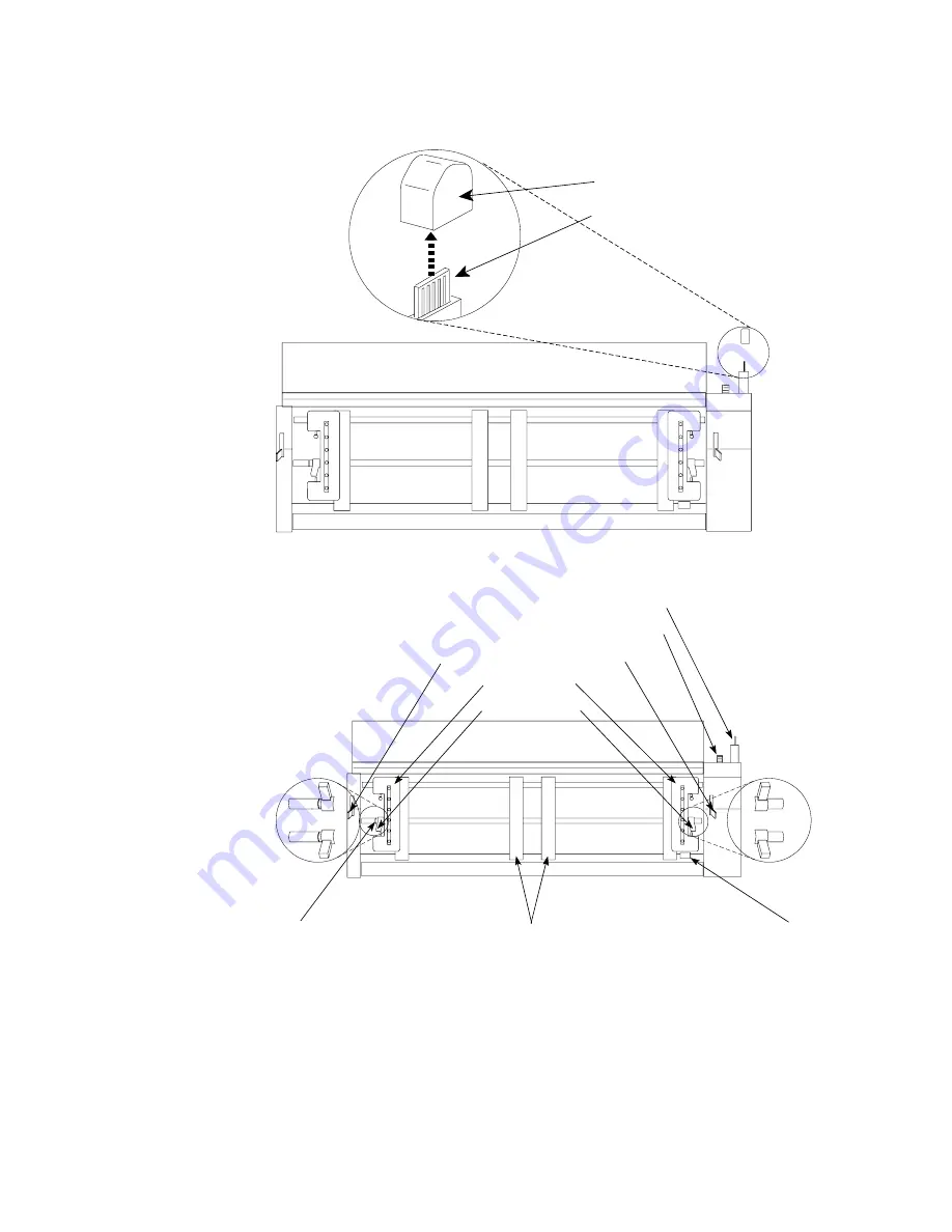
Remove the black protective cap (connector tab cap) from the electrical
connector located on the forms tractor.
El e c t r i c a l C o n n ec t o r Tab
Connector Tab Cap
4.
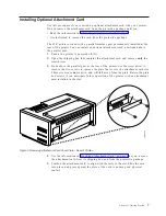
Stand facing the front of the printer. Hold the forms tractor with the tractor
doors toward you and the electrical connector tab on the right.
Unlocked
Locked
Unlocked
Locked
Locking Levers
Electrical Connector Tab
Left Tractor
Alignment Mark
Tractor Doors
Forms Jam Sensor
Spacers
Drive Gear
Tractor Unit Release Levers
5.
With both hands supporting the round tractor shaft, gently push the forms
tractor upward until
a.
The forms tractor clicks on both sides
b.
Both forms tractor release levers are in the locked (up) position
c.
The electrical connector tab is fully seated in the connector
d.
The bottom of the forms tractor is level with (same amount of space from)
the base of the printer
16
4247 Model 003 User’s Guide
Summary of Contents for 4247 Model 003
Page 1: ...4247 Printer Model 003 User s Guide S544 5780 01 IBM ...
Page 2: ......
Page 3: ...4247 Printer Model 003 User s Guide S544 5780 01 IBM ...
Page 46: ...36 4247 Model 003 User s Guide ...
Page 62: ...52 4247 Model 003 User s Guide ...
Page 84: ...74 4247 Model 003 User s Guide ...
Page 86: ...76 4247 Model 003 User s Guide ...
Page 126: ...116 4247 Model 003 User s Guide ...
Page 152: ...142 4247 Model 003 User s Guide ...
Page 168: ...158 4247 Model 003 User s Guide ...
Page 184: ...174 4247 Model 003 User s Guide ...
Page 186: ...176 4247 Model 003 User s Guide ...
Page 188: ...178 4247 Model 003 User s Guide ...
Page 190: ...180 4247 Model 003 User s Guide ...
Page 194: ...184 4247 Model 003 User s Guide ...
Page 331: ...9 Reload the forms Chapter 20 Problems 321 ...
Page 332: ...322 4247 Model 003 User s Guide ...
Page 351: ...that of the power cord or plug whichever is less Appendix A Printer Specifications 341 ...
Page 352: ...342 4247 Model 003 User s Guide ...
Page 391: ......


