WARNING!
During installation the installing expert must verify that the circuit of which is interrupted
by the immobilizer does not trigger an error code in the on-board computer of the vehicle
that aff ects the operational capability of the vehicle. It is important to power the immobilizer
from a wire that is controlled by the ignition switch and provides constant power during the
start up procedure. Once installation is complete, after having become familiar with informa-
tion outlined in the chapter on using the smartphone application, the operator of the vehicle
should verify if it really is possible to prevent the starting of the engine.
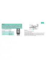
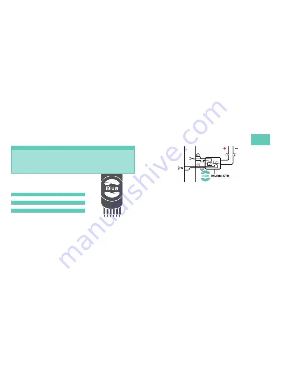
The wiring diagram of iBlue Immobilizer
Wiring is summarised in the following table:
Wire number
Function
1
+12V (ACC)
2
Earth
3
Relay 1 output A
4
Relay 1 output B
5
Relay 2 output A
6
Relay 2 output B
Maintenance
The device does not require any maintenance.
Functions of the iBlue Immobilizer
If turned on/armed, the immobilizer prevents the starting of the engine after turning the ignition
key. The device remains turned on/armed until we enter the proper PIN code. After entering the
proper PIN code, the device is disconnected.
When disconnected, the immobilizer does not prevent the starting of the engine. It is only possi-
ble to terminate the disconnected status by turning ignition off . Within 30 seconds after ignition
is turned off , the immobilizer gets armed automatically.
ENGLISH
1 2 3 4 5 6
Summary of Contents for immobilizer
Page 1: ...Immobilizer User Guide ...


