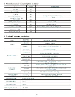
iBeam TE-360 User Manual Download Page 13

12

9

Introduction


of


the


the main menu and sub-menu options

1

)

Press the OK button 

on the remote control 
to select playback

4

)

Return to the main 

menu,select the video 
settings,press the OK 
button


to enter the video 

settings

7

)

Various control settings 

options

vehicle width
vehicle length


517cm

left offset

160cm

right offset

160cm

one key for joint

return

200cm

13

)

Select setting up 

and press OK button 
to enter

2

)

Press OK to select search 

range

5

)

video settings 

for each


function 

selection

8

)

Select  surround  view  smart 

joint,and  press  OK  button  to 
enter  the  surface  of  surround 
view joint parameter input.

11

)

Return to main 

menu,select maintain button 
and press OK button to 
enter.

14

)

Select the left and 

right picture adjustment 
setting and press OK 
button to enter

6

)

return to the main 

menu,select control 
settings,press the OK 
button to enter control 
settings

9

)

after parameter 

input,select one key joint 
and press OK button to 
enter automotive joint.

12

)

To see the 

various function of 
maintain surface

15

)

Enter the single picture view 

of the direction indicator lamp 
and use remote control to 
compress/remove to adjust

Summary of Contents for TE-360

Page 1: ...TE 360 User Manual iBeamUSA com MetraDealer com techsupport metra autosound com TECH SUPPORT l J 800 253 8324 ...

Page 2: ...before installation 5 Guide of cables installation 6 Position and orientation of the cameras installation adjustment 7 Placement of the measuring tape and checkerboard cloth 8 Placement of the measuring tape and checkerboard cloth 9 Introduction of the the main menu and sub menu options 10 Precautions ...

Page 3: ...2 Introduction of 360 Surround view System 1 Product features Panoramic View Front View Right View Left View Rear View System Host ...

Page 4: ...nd at night While driving the display will show left or right camera in real time view on display when either signal is engaged While parking the display will show rear camera in real time view when in reverse gear The display will show front camera in real time view when in drive mode In all circumstances rear view will be the priority With each camera 180 degree Wide Angle Camera is your extra p...

Page 5: ...4 Parallel parking Reversing Blind area of turn Low obstacle The narrow road Front view of abrupt slope Common Uses ...

Page 6: ...tion Language Interface Video input Video output Video Display Video standard c m o a m gp e c reo sm sip or n e i s Turn Left Turn Right Reversing Data storage Software upgrade Support SD upgrade 9 36V 440mA 30 80 C Performance Indicators Chinese English Graphical Menu Interface OSD Menu 4 ch dual video input Single channel dual video output Surround view overlooking PAL NTSC H 264 Main profile c...

Page 7: ...small red wire cannot connect with reserving light or any iron please cut off the positive wire of the original reserving light if the automobile once installed has the reserving camera 5 Guide of cables installation 1 The main box connection diagram below diagram Cable Numbers Cable Pictures Way of connection DC extend cable Remote control receiver cable Camera extend cable 2 Referring to above i...

Page 8: ...ion B when install the left and right cameras please check and see the distance if same from the front back wheels to the lower end of screen according to AV1 AV2 if not same please rotate the left and right cameras to reach same distance as image 1 A B Note the location installation and mounting opening way of the left and right cameras Camera mounting drill diameter is 19 2mm try to put the hole...

Page 9: ... button on the remote controller choose OK button choose set up button choose surround view and smartjoint AV3 show the front camera on display pull out the measuring tape and you can see the measuring tape location from the display Put the 1 6m the wider sized check board cloth close to measuring tape and put in the center of the car Placement of the front checkerboard cloth and measuring tape pu...

Page 10: ...e put the tape just outside of the bumper put the cloth close to the tape and in the center of the car Placement of the left checkerboard cloth and measuring tape put the measuring tape close to the front back wheel put the cloth under the left rear view mirror ...

Page 11: ...ck wheel put the cloth under the right rear view mirror 8 Adjustment of surround view Pic 1 vehicle width vehicl e length left and right offset Note the left and right checkerboard cloth should be at the same lever of the measuring tape correction return checker board cloth measuring tape measuring tape Pic 2 ...

Page 12: ... please check the reason in the following ways lens if there is dust and dirt 3 according to the system reminder return to recalibrate again checker board cloth front measuring tape Note 1 Note that the exact binding site of the measuring tapes 2 left and right tapes should be put close to the wheels 3 the checkerboard cloth should put on the binding sites of the integer on the tape start end vehi...

Page 13: ...gs for each function selection 8 Select surround view smart joint and press OK button to enter the surface of surround view joint parameter input 11 Return to main menu select maintain button and press OK button to enter 14 Select the left and right picture adjustment setting and press OK button to enter 6 return to the main menu select control settings press the OK button to enter control setting...

Page 14: ...10 Precautions ...

Page 15: ..._______________________________________________________________ _______________________________________________________________________________ _______________________________________________________________________________ _______________________________________________________________________________ _______________________________________________________________________________ ________________...

Page 16: ...and negative pole otherwise the fuse will blow immediately for security protection If it happens please replace the blown fuse with a new one with same specification after connecting properly to the right pole Don t randomly increase the current rating of the fuse and NEVER use metal wire as a substitute KNOWLEDGE IS POWER Enhance your installation and fabrication skills by enrolling in the most r...

Reviews: