INSTALLATION AND OPERATION INSTRUCTIONS
3-6
HC SERIES BOILERS
HC 13-50, HC 23-84, HC 29-106, HC 33-124, HC 20-125, HC 33-160
NOTE
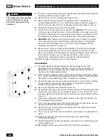
The safety warning regarding
burner refractory on page
4-2 of this manual must be
observed.
3.
There is no need to drain the boiler’s water unless the boiler will be subject to
freezing conditions while the boiler is off.
4.
Remove the front cover and allow the boiler to cool.
5.
Disconnect the flue pipe from the condensate tray by rotating the nut
counter-clockwise about 1/4 turn. Slide the flue pipe up and dis-engage the
bottom of the flue pipe from the condensate tray and slide down to remove.
6.
Unplug the electrical connector at the gas valve.
7.
Loosen both the lower gas valve connection nut.
NOTE:
There is an O-ring
in the lower gas connection and an O-ring and orifice in the upper gas valve
connection. Place these in a safe location to be used for re-assembly. Cover
the gas piping connections to prevent debris from entering the gas piping.
8.
CAUTION:
When removing the heat exchanger cover in step 9, be careful
not to damage the burner and refractory material located on the opposite
side of the heat exchanger cover. Use caution when handling refractory
materials.
See Caution on page 4-2.
9.
Remove all 9 – 6mm hex bolts and lock washers from the heat exchanger
cover and carefully remove the front cover complete with the fan and the
gas valve attached. Carefully inspect the gasket sealing the heat exchanger
to the heat exchanger cover for damage, hardness, cracks, and or
discoloration. If damaged in any way the gasket must be replaced.
10.
Place the heat exchanger cover in a safe location.
RE-ASSEMBLY
1.
Carefully inspect the gasket sealing the heat exchanger to the heat
exchanger cover for damage, hardness, cracks, and/or discoloration. If
damaged in any way the gasket must be replaced. Inspect and clean if
necessary the mating gasket surface.
2.
Place the heat exchanger cover onto the heat exchanger and loosely install
the 9 – 6mm hex bolts and lock washers removed in step 9. Tighten the 6mm
hex bolts in a cross pattern as shown in
diagram on this page.
3.
Connect the gas line to the gas valve ensuring the O-ring is in place. Tighten
the gas valve nut. Ensure the upper gas valve connection is tight. Re-
connect the gas valve electrical connection.
4.
Re-connect the electrical connections to the fan.
5.
Re-install the flue pipe to the vent connector at the top of the boiler and to the
condensate tray. Tighten the nut clockwise about 1/4 turn. Ensure the nut is
properly engaged. Hand tighten only, Do Not Use any tools to tighten the flue
pipe nut.
6.
Inspect the condensate trap for debris. Remove and clean if necessary. Fill
the condensate trap with water.
7.
Turn on the gas supply valve to the boiler and inspect for gas leaks. Use an
approved leak detection solution; soap test all joints.
8.
Ensure the boiler is full of water and purged of air if the boiler was drained
during dis-assembly - step 3.
9.
Turn on the power to the boiler and create a call for heat or for domestic hot
water.
10.
Inspect the gasket around the heat exchanger cover and flue pipe
connections for leaks.
11.
Check flue gases for proper combustion.
See Section 3.3 Commissioning
for
proper adjustments.
12.
Re-install the boiler cover and set the boiler into normal operation.

