12
AGS103T User Manual
2.1.2
Mini-PCIe & M.2 Cards Installation / Replacement
After removing the bottom cover, follow the instructions below.
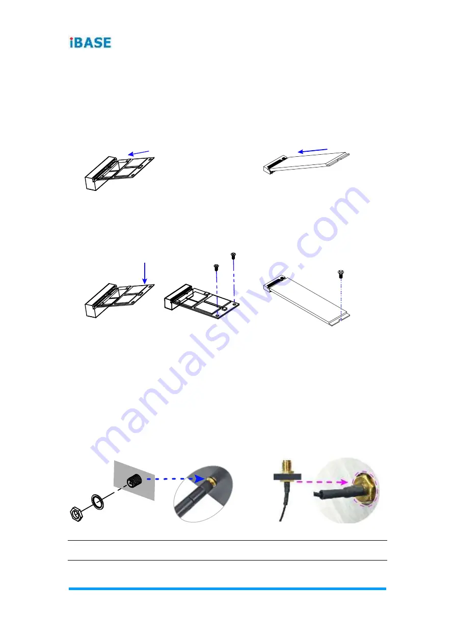
1. Locate the mini-PCIe or M.2 slot, align the key of the card to the interface,
and insert the card slantwise.
Mini-PCIe card:
M.2 card:
2. Push the card down and fix it with the supplied 2 flat head screws for the
mini-PCIe card and with one screw for M.2 card.
Mini-PCIe card:
M.2 card:
2.1.3
WiFi / 3G / 4G Antenna Installation
Thread the WiFi / 3G / 4G antenna extension cable through an antenna hole of
the front I/O cover and fasten the antenna as shown below. Then apply
adhesive to the edge of the hex nut behind the front I/O cover to prevent the
extension cable from falling if the cable becomes loose.
1. Thread and fasten the hex nut and the
washer. Then install the antenna.
2. Apply adhesive around here.
Info:
The diameter of the nut is around 6.35 mm (0.25”-36UNC).
Summary of Contents for AGS103T
Page 8: ......
Page 16: ...8 AGS103T User Manual AGS103TS with Wall Mount Brackets AGS103TS with DIN Rail Mount Optional ...
Page 28: ...20 AGS103T User Manual 2 3 Motherboard Jumper Connector Locations SL100 Motherboard ...
Page 29: ...Hardware Configuration AGS103T User Manual 21 2 IP802 Carrier Board ...
Page 39: ...Hardware Configuration AGS103T User Manual 31 2 2 4 24 J11 Board to Board Connector ...
Page 61: ...BIOS Setup AGS103T User Manual 53 4 Serial Port 2 Configuration ...
Page 62: ...54 AGS103T User Manual Serial Port 3 Configuration ...
Page 63: ...BIOS Setup AGS103T User Manual 55 4 Serial Port 4 Configuration ...
Page 70: ...62 AGS103T User Manual ...
Page 71: ...BIOS Setup AGS103T User Manual 63 4 ...
Page 72: ...64 AGS103T User Manual ...
Page 76: ...68 AGS103T User Manual A I O Port Address Map ...


