EN
TECHNICAL DATA
Minimum dynamic pressure:_________________________________________________________0.5 bar
Maximum operational pressure:________________________________________________________5 bar
Recommended operational pressure:_________________________________________________1-5 bar
It’s recommended to use a pressure reducer in case of
static pressure superior than 5 bar inside the waterpipe.
Maximum hot water temperature:_______________________________________________________80°C
INSTALLATION, MAINTENANCE AND PRELIMINARY CHECKING PROCEDURE
In
order to get your device work correctly and fi ne in time, must ensure compliance with the
mode of installation and maintenance described in this booklet. Relying on a qualifi ed plumber.
Make sure that the system is free from all debris and impurities existing.
INSTALLATION
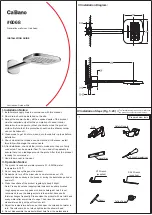
Fig. 1:
Make two holes for the handle MIN Ø28 mm - 1.1 in, MAX Ø35 mm - 1.37 in. Mount the
fi xing set on the platform. From beneath insert the base into the hole, place the gasket in the
seat on the base. Screw the base on the fi nishing ring. Screw the ring to the platform until it is
fully locked. From beneath tighten the fi xing kit until it is fully locked. Engage the handle on the
broach by locking it with the screw.
Fig. 2:
Connect the hoses to the two platforms
Fig. 3:
Drill a hole in the plane Ø35 mm - 1.37 in. Insert the stem of the spout, positioning the
gasket below it. Fix the spout with the fi xing kit.
Fig. 4:
Connect the hose to the spout.
Fig. 5:
In the platform, make a hole Ø32 mm - 1.26 for the shower support. Insert the base insi-
de the base. Place it in the hole of the platform by inserting the gasket. Fix the shower support
with the fi xing kit.
Fig. 6:
Make the hole for the shower support Ø30 mm - 1.18 in the platform. Fit the fi xing set on
the diverter. Place the broach extension on the diverter. From under the top insert the diverter
into the hole, place the gasket in the seat of the base. Screw the base onto the fi nishing ring.
Screw the fi nishing ring until it is completely blocked. From beneath, tighten the fi xing kit until
it is completely locked. Engage the handle on the broach and lock it with the screw.
Fig. 7:
Connect the fl exibles to the diverter as in frame on the image. Connect the sidebody
valves to the hydric system.
After connecting the body to the system, turn on the stopcocks and check that the mixer tap
unit operates correctly. Keep the tap pressurised for a few minutes checking eventual leaks.
CLEANING
In order to obtain a correct cleanliness, exclusively wash them with soap and water, rewash and
dry them with a soft towel and deerskin. Avoid the usage of alcohol, solvents, solid or liquid
detergents which contain corrosive or acidic substances, abrasive sponges, swab with metallic
strings because they could irreversibly compromise the surfaces.
THE USAGE OF THIS KIND OF DETERGNETS DURING THE CLEANING OF THE MIXER EXCLUDE
IB RUBINETTERIE FROM ANY WARRANTY OBLIGATION.
Summary of Contents for BOLD 396 Series
Page 5: ...Fig 1...
Page 6: ...Fig 2...
Page 7: ...Fig 3...
Page 8: ...Fig 4...
Page 9: ...Fig 5...
Page 10: ...Fig 6...
Page 11: ...Fig 7...
Page 12: ......