Page 9
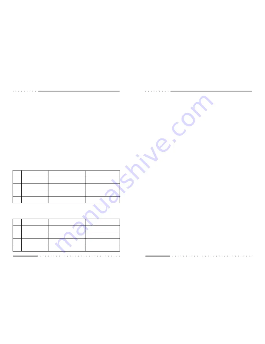
Touchpad Dipswitches when connected to earlier version
Blackbox relay modules (BB-5) for backward compatibility
Function
OFF
(Factory Default)
ON
1
Compressor Delay
Software Selectable
(4 minute default)
4 seconds (max)
2
Lock System
Settings Menu
Allow Access
Deny Access
3
Setpoint Range
15-30°C
(0.5°C increments)
20-25°C
(0.5°C increments)
4
Heat Type
Reversing Valve
Electric Duct Heat
or Cool Only
5.0 Installation and Commissioning
• Ensure all electrical connections are in accordance with the supplied connection dia-
grams and local bylaws.
• Set the Dipswitches on the back of the touchpad according to the notes and tables
below.
• Set all the system settings as mentioned in Section 3.
• If the clock module has been purchased and fi tted, refer to Section 4.0 to confi gure
the clock and automated on/off programs, holidays and daylight savings.
• Operate the controller in heat, cool and try each fan speed setting.
• Ensure that the Delay in the Settings Menu is restored to Safety prior to fi nishing
commissioning.
5.1 Touchpad Dipswitch Confi gurations
Some touchpads are backward compatible with earlier Blackbox versions. The touchpad
will confi gure its dipwitches depending on the relay module it is connected to.
Touchpad Dipswitches when connected to
Blackbox Plus relay module (BBP-5)
Function
OFF
(Factory Default)
ON
1
Menu Lock
Menus
Available
Menus
Locked
2
Setpoint Lock
Setpoint
Adjustable
Setpoint
Locked
3
Setpoint Range
15-30°C
(0.5°C increments)
20-25°C
(0.5°C increments)
4
On/Off Lock
On/Off
Available
On/Off
Locked
Page 2
1.0 Quick Start Options
This controller provides a menu based user interface. The information that can be
displayed at any given time is limited by the screen area of 2x8 character lines. Additional
options are viewed by using the arrow buttons to scroll the information across the screen.
The fl ashing cursor indicates the active area of the screen (generally the top line of the
display). Pressing the enter button will activate the selection highlighted by the fl ashing
cursor.
• To change the setpoint, press the arrow buttons. Once the required temperature has
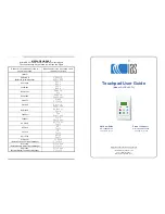
been set the screen will revert to the default display after a short period (see image page 1).
• All standard menu options are accessible by pressing menu at the default display
screen.
• All clock menu options (clock module required) are accessible by pressing menu at
the clock display screen.
• Press the clock button to switch between the default display screen and the clock
display screen.
• The menu button when pressed will access the various menu screens.
• While in the menu screens the menu button, when pressed, takes you back one step.
• The enter button when pressed moves forward through the various screens, selecting
options and saving settings.
• The current active settings appear in CAPITALS.
• The arrow buttons, when pressed in a menu will either cycle the cursor and scroll the
screen through the various options available, or, alter the value of the selected variable.
• Press and hold the arrow button to quickly scroll the selected variable.
2.0 Standard Menu Options
While viewing the default display screen press the menu button to gain access to the
standard menu options. Use the arrow buttons to cycle the cursor to the desired menu
option, then press the enter button to select that option.
Pressing the menu button (or selecting ‘
Exit
’ then pressing enter) will exit the current
selection if required.
2.1 To Change the Mode
Operation:
The Mode controls the operation of the A/C system. Available options are Cool, Heat,
Vent or Auto (automatically switches between cooling and heating as required)
• Select ‘
Set Mode
’ from the standard menu options screen (see section 2.0) and the
mode selection screen will appear. (Quick Tip: Press menu, down, enter)
• Scroll down with the down arrow to select the required operating mode.
• Press the enter button to save the new value and return to the default display screen.


