IAI ROBO Cylinder  RA13R Operating Manual Download Page 19


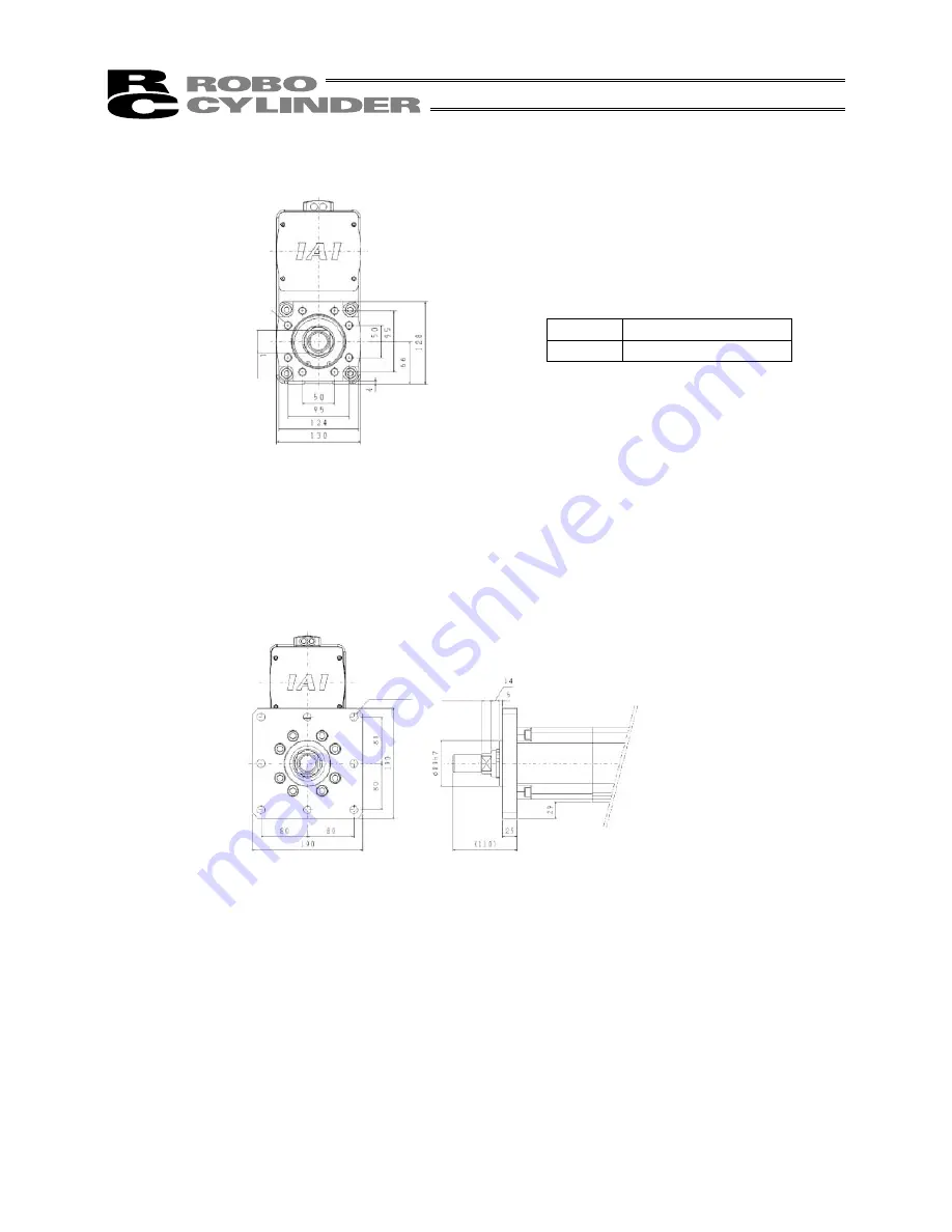
(2)  Using the tapped holes on the rod side 


Tap size 

Maximum thread length 

M12 24 

mm 


Tapped holes are provided on the rod side for mounting. You can use these tapped holes to install the 
actuator. The maximum thread length of rod mounting screws is specified above. Make sure the bolt ends 
do not project through the holes. 
 

(3)  Using a flange (optional) with screws 

An optional flange is available. You can use this flange to install the actuator. 


8-M12, depth 24 

36 ac

ro

s

s

 fla

ts


(w

id

th

 a

c

ro

ss 

fl

a

ts)


8-13, 5 drilled 

16 (width across flats)

Summary of Contents for ROBO Cylinder RA13R

Page 1: ...IAI America Inc ROBO Cylinder Rod Type RCS2 Actuator First Edition Ultra High Thrust Type RA13R Operating Manual ...

Page 2: ...0 mm 35 kg 200 mm 36 kg When transporting or installing the actuator always work in a group of two or more to securely support the actuator body and exercise due caution to prevent injury z Prohibited handling practices Do not hold the rod when transporting the actuator Do not hold the motor cover when transporting the actuator ...

Page 3: ... not result in injury Take note that depending on the situation a failure to heed the directions accompanied by Caution or Note may still result in serious consequences All instructions provide important information Read them carefully and handle the product with due care Keep this operating manual in a convenient place so that it can be readily referenced whenever necessary and also make sure the...

Page 4: ...ause electric shock or injury due to contact with the moving parts z Wire the product correctly by referring to the operation manual Securely connect the cables and connectors so that they will not be disconnected or come loose Failure to do so may cause the product to malfunction or cause fire Operation z Before operating the moving parts of the product by hand for the purpose of manual positioni...

Page 5: ...ing or other operations are performed that cause arc discharge 3 Place subject to electrostatic noise 4 Place with potential exposure to radiation z Do not install this product in places where the product may receive vibration or shock z Provide an emergency stop device in a readily accessible position so the device can be actuated immediately upon occurrence of a dangerous situation during operat...

Page 6: ...ure a control circuit that will cause the work to drop in case of power failure Configure a control circuit that will prevent the table or work from dropping when the power to the machine is cut off or an emergency stop is actuated z Take the following precautions to increase the linear traveling accuracy of the rod and ensure smooth movement of the ball screw 1 Flatness of the mounting surface mu...

Page 7: ... the information carefully to connect the cables properly 1 Do not let the cable flex at a single point 2 Do not let the cable bend kink or twist 3 Do not pull the cable with a strong force 4 Do not let the cable receive a turning force at a single point 6 Do not pinch drop a heavy object onto or cut the cable 5 When fixing the cable provide a moderate slack and do not tension it too tight Steel b...

Page 8: ...degree of flexibility so that the cable will not become too taut when bent z Do not cause the cables to occupy more than 60 of the space in the cable bearer z Do not lay signal lines together with circuit lines that create a strong electric field Cable Cable bearer Power line Signal lines flat cable Duct z Always use a robot relay cable Bending radius r z If a cable bearer is used select one with ...

Page 9: ... 1 Preassembled Actuator 6 5 2 2 Handling the Actuator Assembled with Peripherals 6 6 Operating and Storage Environment 7 6 1 Operating Environment 7 6 2 Storage Environment 7 7 Installation 8 7 1 Installing the Main Body 8 8 Wiring Cable 11 9 Installing the External Brake Connection Box for the Brake Specification 12 10 Maximum Speed 14 11 Load Applied to the Actuator 15 12 Selection Conditions 1...

Page 10: ......

Page 11: ... the power is ON since this is dangerous 2 2 Maintenance and Inspection When doing maintenance and inspection work always shut down the controller power first When doing inspection make sure that no one can inadvertently turn the power ON Make sure that a sign indicating work in progress is clearly visible If several persons are working be sure to watch out for each other s safety In particular ch...

Page 12: ...e to aging Wear of consumable parts from use Noises and other subjective conditions that do not affect function Inappropriate handling by the user or failure to conduct maintenance inspection Modification not performed by IAI or its authorized dealer Breakdown resulting from using a controller not manufactured by IAI Anything caused by an act of God accident fire etc This warranty covers only the ...

Page 13: ...g direction varies depending on the specification of the delivered product Caution Even if you specified a robot cable the cable extending from the actuator is not a robot cable Design an appropriate wiring layout so that this cable will not receive a flexing force The robot cable specification applies to the relay cable Rod Side Right Left Connector box Pulley cover Motor Side Rod tip adapter Alu...

Page 14: ...ied a robot cable the cable extending from the actuator is not a robot cable Design an appropriate wiring layout so that this cable will not receive a flexing force The robot cable specification applies to the relay cable Rod Side Right Left Connector box Pulley cover Motor Side Rod tip adapter Aluminum frame Base Motor bracket Brake housing Rod ...

Page 15: ...he Actuator After It is Unpacked The table below lists the weights of this actuator Stroke Weight 50 mm 33 kg 100 mm 34 kg 150 mm 35 kg 200 mm 36 kg When transporting or installing the actuator always work in a group of two or more to securely support the actuator body and exercise due caution to prevent injury When carrying the actuator exercise care not to hit it against an object structure etc ...

Page 16: ...ates Similarly when lifting the actuator with a forklift place the forks below the skid plates Set down the box carefully to prevent application of impact or bouncing of the box upon landing Once the actuator is unpacked handle the actuator by observing the instructions below 5 2 2 Handling the Actuator Assembled with Peripherals When transporting the unpacked machine preassembled at IAI or custom...

Page 17: ...esigned for use in a chemical environment In general the environment should be one in which an operator can work without protective gear Work space required for maintenance inspection Provide the work space specified below if you want to replace the motor belt etc without removing the actuator 6 2 Storage Environment The storage environment should be similar to the operating environment In additio...

Page 18: ...mounting You can use these tapped holes to install the actuator The maximum thread length of base mounting screws is specified above Make sure the bolt ends do not project through the holes There are also reamed positioning holes which can be used if necessary Reamed hole 2 8H7 depth 10 D M12 depth 18 Tap size Maximum thread length M12 18 mm Stroke ...

Page 19: ...ed holes to install the actuator The maximum thread length of rod mounting screws is specified above Make sure the bolt ends do not project through the holes 3 Using a flange optional with screws An optional flange is available You can use this flange to install the actuator 8 M12 depth 24 36 across flats width across flats 8 13 5 drilled 16 width across flats ...

Page 20: ...10 4 Using foot brackets optional Optional foot brackets are available You can use these brackets to install the actuator D 13 5 drilled ...

Page 21: ...radial wire duct to limit the load on the cable Never cut and or reconnect the cables supplied with the product for the purpose of extending or shortening the cable length The standard cable provides excellent flexibility but it is not a robot cable Use a robot cable if the cable is to be stored in a moving cable duct cable bearer etc For cable modification please contact IAI ...

Page 22: ...th a brake an external brake connection box must be installed z External brake connection box Model RCB 110 RA13 0 Front view Rear view External switch connector 24 V power supply connector Power ON switch Connector for actuator 1 Connector for controller 1 Connector for actuator 2 Connector for controller 2 ...

Page 23: ...er 1 are used It is also possible to use the connectors for actuator 2 and controller 2 2 Connect a 24 V power supply to the 24 V power supply connector on the external brake connection box and input 24 V power 3 Turn on the power ON switch The external brake connection box will be activated Connection diagram with controller SCON 400 W or above Actuator Motor cable Encoder cable Encoder cable Ext...

Page 24: ...00 mm 62 mm sec Caution If the actuator is used at speeds beyond the maximum level noise may increase or vibration may generate due to resonance of the ball screw shaft and such increased noise or vibration may consequently reduce the service life of the product If each actuator is used independently write a program conforming to the maximum speed of the actuator refer to the table above If multip...

Page 25: ...e rod center to the work s center of gravity L2 Distance from the actuator mounting surface to the work s center of gravity 0 07 The rod can receive a load only when all of conditions 1 to 3 are satisfied If any condition is not satisfied take an appropriate measure such as providing an external guide to prevent the rod from receiving a load Do not allow the rod to receive any load torque exceedin...

Page 26: ...itions The following three conditions must be met before the ultra high thrust actuator can be used Condition 1 The push time does not exceed the specified time Condition 2 The thrust for continuous operation does not exceed the rated thrust of the ultra high thrust actuator throughout the cycle Condition 3 Push motion operation is performed only once per cycle Each condition is explained by using...

Page 27: ...command value as shown in the table below Find the maximum push time for each command by referring to this table and make sure the push time does not exceed the specified duration Take note that a failure to adhere to this table may result in actuator problems Table 1 Push Times Fig 1 Push Time Push command value Maximum push time s Push command value Maximum push time s ...

Page 28: ... upward motion in vertical application Move at a constant speed in upward motion in vertical application Decelerate in upward motion in vertical application Stand by in vertical application 1 If an external guide or other similar component is installed the traveling resistance must be considered M Mass of moving part kg m Loaded mass kg d Commanded acceleration deceleration m s2 If the calculated ...

Page 29: ... 3 s Standby time 2 s Move 50 mm downward perform push motion operation move 50 mm upward and stand by for 2 sec The operating conditions for upward and downward movements are the same The graph on the right illustrates the above operation pattern Now calculate the necessary values by following the selection procedure Condition 1 Check the push motion operation time From Table 1 on p 15 the push t...

Page 30: ... during deceleration 19 60 mm Speed 62 mm s 0 174 s Travel distance during acceleration deceleration Acceleration deceleration rate 98 mm s2 x Acceleration deceleration time t1a 2a 1d 2d 0 632 s 2 2 19 60 mm to 3s tw 2 s t 7 88 s From the above the following result is obtained Fw 12113 N Since this is greater than the rated thrust of 10200 N specified for the ultra high thrust actuator with 1 25 2...

Page 31: ...1 year thereafter 1 Apply the grease to the rod ball spline slide surface when dry surface is observed at the start of operation or every three months of operation 13 2 Visual Inspection of the Machine Exterior Check the following when doing the visual inspection Body Loose mounting bolts Cables Damage to cables or connection to connector box General Unusual noise or vibrations 13 3 Cleaning Clean...

Page 32: ...lled at the grease feed port When the tapered plug has been removed the grease nipple appears 2 Insert the grease gun into the grease nipple and add grease Use a grease gun corresponding to the diameter of the grease nipple Nipple diameter 4 3 After a sufficient amount of grease has been added close the grease feed port with the tapered plug with hexagonal hole 4 Turn on the controller power and r...

Page 33: ... may vary slightly from the diagram Keep the current limiting value at 20 or above because any lower setting may cause the push force to fluctuate The traveling speed is fixed to 10 mm s during push motion operation This diagram assumes a push speed of 10 mm s Take note that the push force may decrease when a different push speed is used Depending on the operating conditions the push force may als...

Page 34: ...p the shield to the hood Drain wire or braided shield wire White blue in the Color field indicates that the cable is white and the insulator is blue White blue White yellow White red White black White purple White gray Wire size Color Signal No Signal Color Wire size Signal Color Wire size White orange White green Brown blue Brown yellow Brown red Brown black White blue White yellow White red Whit...

Page 35: ...25 ...

Page 36: ...26 ...

Page 37: ... 467 9900 FAX 630 467 9912 New Jersey Office 7 South Main St Suite F Marlboro NJ 07746 TEL 732 683 9101 FAX 732 683 9103 Website www intelligentactuator com Ober der Röth 4 D 65824 Schwalbach am Taunus Germany TEL 06196 88950 FAX 06196 889524 The information contained in this document is subject to change without notice for the purpose of product improvement Copyright 2007 Feb IAI Corporation All ...

Reviews: