


Starting Procedures
When using this product for the first time, make sure to avoid mistakes and incorrect wiring by referring to
the procedure below. “PC” stated in this section means “PC software”.
Head Office: 577-1 Obane Shimizu-KU Shizuoka City Shizuoka 424-0103, Japan
TEL +81-54-364-5105 FAX +81-54-364-2589
website: www.iai-robot.co.jp/
Ober der Röth 4, D-65824 Schwalbach am Taunus, Germany
TEL 06196-88950 FAX 06196-889524
SHANGHAI JIAHUA BUSINESS CENTER A8-303, 808, Hongqiao Rd. Shanghai 200030, China
TEL 021-6448-4753 FAX 021-6448-3992
website: www.iai-robot.com
Technical Support available in USA, Europe and China
Head Office: 2690 W. 237th Street, Torrance, CA 90505
TEL (310) 891-6015 FAX (310) 891-0815
Chicago Office: 1261 Hamilton Parkway, Itasca, IL 60143
TEL (630) 467-9900 FAX (630) 467-9912
TEL (678) 354-9470 FAX (678) 354-9471
website: www.intelligentactuator.com
Atlanta Office: 1220 Kennestone Circle, Suite 108, Marietta, GA 30066
825 PhairojKijja Tower 12th Floor, Bangna-Trad RD., Bangna, Bangna, Bangkok 10260, Thailand
TEL +66-2-361-4458 FAX +66-2-361-4456
↓
→
No →
→
No →
Contact us or our distributor.
↓ Yes
No →
→
Check Item
Is SYS* on the status LED display for the driver on the axis
number indicated for the servo-on turned on in green?
↓ Yes
Test Run Adjustment 1
Cancel the emergency stop, remove the work piece, set
to low speed and check the operation in the command
of the host controller (PLC, XSEL, etc.).
After doing so, set the speed back to the indicated, put
back the work piece and check the operation.
↓ Yes
← Yes
No →
↓ Yes
No →
↓ Yes
↓
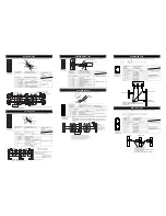
Servo ON
Turn the servo on for all the connected axes by operating a teaching tool such as PC.
Initial setting and operation mode select
Conduct the initial setting using the PC software, and make the operation mode select and other necessary selections.
Register the operation mode selected in the initial setting to MSEP Gateway using Gateway Parameter Setting Tool.
Check of Packed Items
Are there all the delivered items?
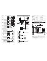
Installation and Wiring
Perform the installation of and wiring for the actuator and controller.
Power Supply and Alarm Check
Connect a teaching tool such as the PC software, set the operation
mode setting switch to “MANU” side and turn the power ON.
Select “Teach Mode 1 Safety Speed Effective/Prohibit PIO Startup”
on a teaching tool such as the PC software.
Point Check Item
• Is frame ground (FG) connected?
• Has the noise countermeasure been taken?
Check Item
Is SYS in Status LEDs
turned ON in green?
Connect the teaching tool such as
PC to confirm the content of alarm
and have an appropriate treatment.
Caution
Please perform this process with the actuator away from the mechanical end or interfering subjects as much as
possible.
Put the actuator away if it interferes with surroundings. It may generate an alarm if the actuator hit the mechanical
end or interfering subjects when the servo is turned ON.
The slider may get slightly dropped by self-weight if servo ON and OFF is repeatedly performed at the same position.
Be careful not to pinch the hand or damage the work.
If an alarm is generated, connect the PC or
teaching pendant and check the content of
the alarm to have the right treatment.
Safety Circuit Check
Does the emergency stop circuit (drive cutoff circuit)
work properly and turn the servo OFF?
Check the emergency stop circuit.
Check Item
Any vibration or
abnormal noise?
Check if there is any problem with the installation
of the actuator and the condition of the actuator
use exceeds the ranges of the rated values.
Adjust the servo if necessary.
Test Run Adjustment 2
1) Put the operation mode setting switch to AUTO side.
2) Output the operation command from PLC to the controller and check the system operation.
Target Position Setting [Except for simple direct mode and direct
numerical specification mode]
Set the target position in “Position” Box in each position table.
Manual No.: ME0300-4B


