


Options
* Please check the Options reference pages to confirm each option.
Name
Option code
Reference page
RCON-EC connection specification (Note 1) (Note 2)
ACR
19
Brake
B
19
Cable exit direction (bottom)
CJB
19
Cable exit direction (left)
CJL
19
Cable exit direction (right)
CJR
19
Cable exit direction (top)
CJT
19
Non-motor end specification
NM
19
PNP specification (Note 1)
PN
19
Split motor and controller power supply specification (Note 1)
TMD2
19
Wireless communication specification (Note 2)
WL
19
Wireless axis operation specification (Note 2)
WL2
19
(Note 1) If the RCON-EC connection specification (ACR) is selected, the PNP specification
(PN) and split motor and controller power supply specification (TMD2) cannot be
selected. As well, the interface box and conversion cable are not included.
(Note 2) When selecting the RCON-EC connection specification (ACR), the wireless
communication specification (WL) and wireless axis operation supported specification
(WL2) cannot be selected. When using wireless communication with RCON-EC
connection, separately prepare the interface box, conversion cable, and power / I/O
cable connector which are available as options. Please refer to P. 23 for details.
Separately Sold Options
Actuator Cable Length
Cable code
Cable length
1 ~ 3
1 ~ 3m
4 ~ 5
4 ~ 5m
6 ~ 10
6 ~ 10m (Note 1)
(Note 1) When connecting via the interface box, 9m is the maximum available.
(Note) Make sure that the total length along with the power I/O cable connector is 10m
or less.
Power I/O Cable Connector Length
Standard Connector Cable
Cable code
Cable length
User wiring specification
(flying leads)
0
Without cable
Terminal block supplied (Note 1)
1 ~ 3
1 ~ 3m
4 ~ 5
4 ~ 5m
6 ~ 7
6 ~ 7m
8 ~ 9
8 ~ 9m
(Note 1) Only terminal block connector is included. When selecting RCON-EC connection
specification (ACR) as an option, select “0”. Terminal block connector is not
included. Refer to P. 26 for details.
(Note) Robot cable.
4-way Connector Cable
Cable code
Cable length
S1 ~ S3
1 ~ 3m
S4 ~ S5
4 ~ 5m
S6 ~ S7
6 ~ 7m
S8 ~ S9
8 ~ 9m
(Note) Robot cable.
CB-EC2-PWBIO
-RB
supplied
CB-EC-PWBIO
-RB
supplied
User wiring specification
(flying leads)
Name
Model
Reference page
Interface box
conversion cable
CB-CVN-BJ002
28
RCON-EC connection specification
power / I/O cable
(standard connector cable)
CB-REC-
PWBIO
-RB
29
RCON-EC connection specification
power / I/O cable
(4-way connector cable)
CB-REC2-
PWBIO
-RB
29
Air cylinder
compatible mounting plate
EC-CSB-T3-(stroke)
20
RCON-EC connection specification
interface box
for split motor and controller power supply
(wireless specification)
ECW-CVNWL-CB-
ACR
28
(Note) The power / I/O cable connector is a robot cable.
Please indicate the cable length in
. (Ex.: 010 = 1m)
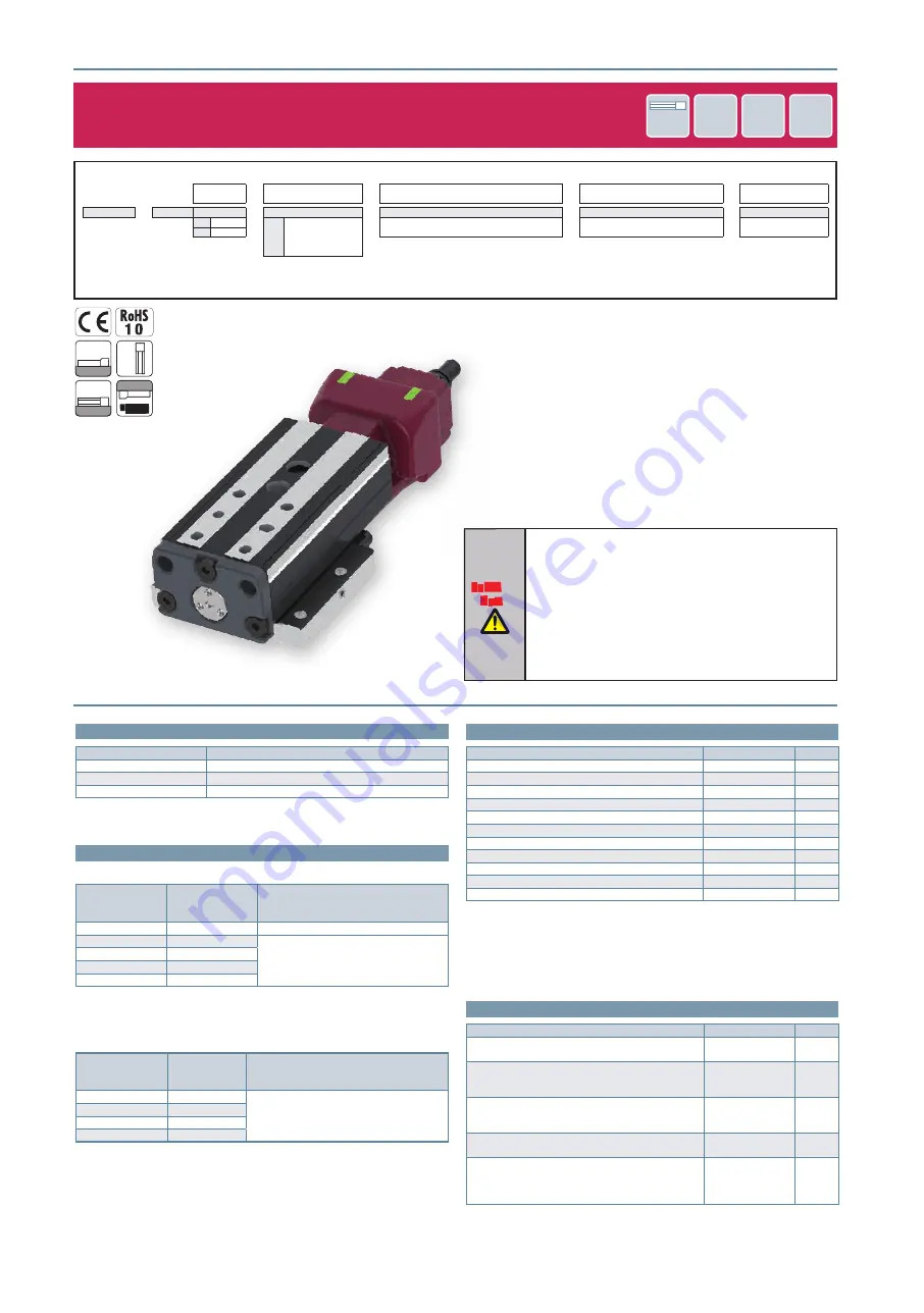
EC-T3
Lead
Screw
24
V
Pulse
Motor
Body Width
30
mm
Coupled
Motor
EC
EleCylinder
Horizontal
Ver
tical
Side
Ceiling
EC-T3
16
Model Specification Items
EC
-
T3
-
-
-
-
Series
-
Type
Lead
-
Stroke
-
Actuator cable length
-
Power I/O cable connector length
-
Options
M
4mm
10
10mm
See actuator cable length table below
See power I/O cable connector length
table below
See options below
L
2mm
~
~
50
50mm
(every 10mm)
Selection
Notes
(1) “Main Specifications” displays the payload’s maximum value.
Please refer to “Table of Payload by Speed/Acceleration” for more
details.
(2) If performing push-motion operations, refer to the “Correlation
Diagrams between Push Force and Current Limit.” The push
forces listed are only reference values. Please refer to P. 22 for
applicable notes.
(3) Pay close attention to the mounting orientation. Please refer to
P. 5 for details.
(4) For the table displacement amount, refer to the instruction
manual.