background image

10     |     Discover more i3 products on www.i3-technologies.com 

Product Overview 

I/O Interface 

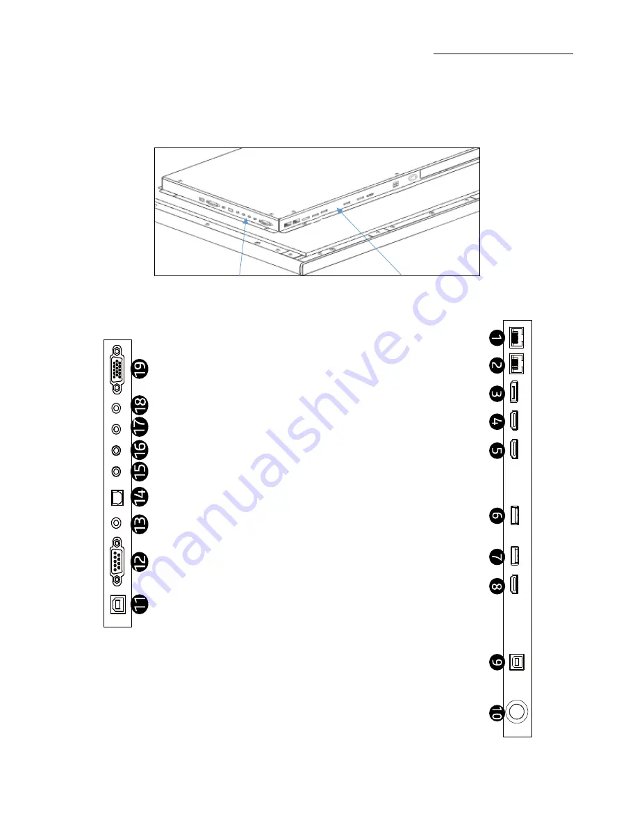
The touch display’s input and output connectors are located at the rear, on the left side and bottom of the display. 
They are shown in the images below and described in the following paragraphs. Please note that connectors may vary 
in some derivate models. Please refer to the individual product sheets for verification. 


Bottom ports 

Side ports 


VGA IN 
 
 
Audio IN 3.5mm jack 
 
AV OUT 
YPbPr IN 
 
AV IN 
 
SPDIF OUT 
 
Audio Out 3.5mm jack 
 
 
RS232 IN 
 
 
Touch USB (HDMI 2, VGA, DP) 


LAN IN 


LAN OUT 


DisplayPort IN 


HDMI 2 IN (ARC) 


HDMI 1 IN (MHL) 


USB 3.0 


USB 3.0 


HDMI OUT 


Touch USB (HDMI 1) 


Power Button (hold) 

Menu Button (press) 


All manuals and user guides at all-guides.com

Summary of Contents for i3TOUCH P5510

Page 1: ...www i3 technologies com All manuals and user guides at all guides com a l l g u i d e s c o m...

Page 2: ...n a triangle is intended to warn that parts inside the product are a risk of electric shock ATTENTION The exclamation point within a triangle is intended to warn users that important operating and ser...

Page 3: ...heavy objects on the power cord This may damage the power cord which may result in electric shock or fire Immediately replace the power cord when any damage is noticed CAUTION Electric Safety Follow...

Page 4: ...y from children Children may suffocate or swallow the smaller parts Do not install the product on unstable surfaces like insecure shelves or sloped surfaces etc The product may fall and become damage...

Page 5: ...Support contact person Before moving the product turn off the power switch and disconnect the power cord antenna cable and all other connected cables If the product generates abnormal sounds a burnin...

Page 6: ...on using the product for a longer time Dust accumulation with heat can cause a fire electric shocks or electric leakage Use the product at the recommended resolution and frequency to prevent eye stra...

Page 7: ...t and remove the top of the box Unpack the smaller contents of the box Check the table below and verify if all accessories are included in the box Remove the styrofoam and plastic bag from the product...

Page 8: ...are subject to change without notice Refer to the dimensions on product sheets prior to installing the product Unit mm Model Name 1 2 3 4 5 VESA hole AxB 1280 0 781 0 1212 0 683 0 96 400x400 1498 2 89...

Page 9: ...nel and microprocessor controlled main board It is designed to meet the demanding and rigid performance requirements of education schools public premise corporate and industrial applications Power Swi...

Page 10: ...lowing paragraphs Please note that connectors may vary in some derivate models Please refer to the individual product sheets for verification Bottom ports Side ports VGA IN Audio IN 3 5mm jack AV OUT...

Page 11: ...the product with dedicated hardware applicable for your installation environment ea wall reinforcements dedicated wall plugs and screws for certain types of wall constructions etc Hanging Profiles Fix...

Page 12: ...rts for Touch connection The Touch USB port on the left side nr 9 is dedicated for use with the HDMI 1 video input source The other Touch USB port on the bottom nr 11 is for use with other video input...

Page 13: ...n the Home Page you can also access the device settings with the Settings button i3NOTES Use the i3NOTES application to take notes or use during presentations or educational events by writing with fin...

Page 14: ...Pull up Bar This menu can be accessed on every signal source input and provides quick access to signal source switching image settings volume control and brightness settings Press Return to return to...

Page 15: ...ources at any time A green indicator will show the signal sources that are active and can be switched to Display Setting Picture sound and additional settings Open the Display Settings on the Pull up...

Page 16: ...min 55 00 4A 05 A4 22 Set Sleep Timer 120 min 55 00 4A 06 A5 23 Set Sleep Timer 180 min 55 00 4A 07 A6 24 Se Aspect 55 00 4C 00 A1 25 Volume up 55 00 0C 00 61 26 Volume down 55 00 0E 00 63 27 Return...

Page 17: ...14 A3 77 Set BASS 30 55 00 3A 1E AD 78 Set BASS 40 55 00 3A 28 B7 79 Set BASS 50 55 00 3A 32 C1 80 Set BASS 60 55 00 3A 3C CB 81 Set BASS 70 55 00 3A 46 D5 82 Set BASS 80 55 00 3A 50 DF 83 Set BASS 90...

Page 18: ...d cables and connectors Check the video resolution and frequency Out of Range will be briefly displayed if a input source signal exceeds a supported resolution Refer to the Supported Resolutions secti...

Page 19: ...ithin a range compatible with the product Then change the screen settings if required by referring to the Additional Information on the product menu and the Standard Signal Mode Table There are shadow...

Page 20: ...l It may cause permanent damage on the unit or panel Use a clean soft lint free cloth or apply a small amount of non ammonia non alcohol based glass cleanser to achieve maximum cleaning Disclaimer The...

Page 21: ...ng per two different types of panels native resolution VGA Timing HDMI DP Timing 1 640x480 60Hz 1 720x480i 60Hz 2 800x600 60Hz 2 720x480p 60Hz 3 1024x768 60Hz 3 1280x720p 60Hz 4 1280x960 60Hz 4 1920x1...

Page 22: ...22 Discover more i3 products on www i3 technologies com NOTES All manuals and user guides at all guides com...

Page 23: ...User Manual 23 NOTES All manuals and user guides at all guides com...

Page 24: ...www i3 technologies com AUTHORIZED DISTRIBUTOR All manuals and user guides at all guides com...

Reviews: