background image


Getting Started 

15 

Viewing Live Video 

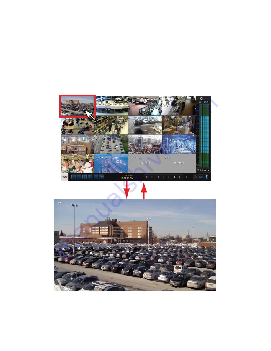
After logging in, you will be able to view live video from all connected cameras in a multi-screen view. 
Where camera is out of order, black screen will be displayed with text “VIDEO LOSS”. 
Call your installer for service if a previously working camera can no longer be seen in the Live view screen. 
In the example below, video loss has been detected on Channels 15 and 16. 
To bring a specific camera screen into full screen mode, position your mouse cursor over the camera video stream on the screen and 
double-click the left mouse button. The camera will be maximized on the screen. 
Double-click on the screen again to return to the multi-screen display. 


Summary of Contents for VEO 16

Page 1: ...Quick Operation Manual 2014 i3 International Inc The contents of this user manual are protected under copyrights and computer program laws 16 VEO EMBEDDED DVR Rev 141112 v 1 3 ...

Page 2: ...10 Alarm I O Connection 11 Getting Started 12 Front View 12 Log In 13 Log Out 13 System Shutdown 13 Live Screen 14 Viewing Live Video 15 Timeline 16 Status Bar 16 View Event Log 17 Quick Menu 19 Digital Zoom 19 Instant Snapshot Export 20 PTZ Mode 25 Preset Recall 27 Creating New Presets 27 Preset Scan 28 Preset Tour 29 Video Search 31 Search Window 31 Playback Window 33 Video Export 34 Exported Vi...

Page 3: ...uality Settings 45 Motion Sensor 48 Sensitivity Level 49 Motion Detection Area 49 Web Viewer 51 IP Address Information 51 Connecting via Web Browser 53 Search Video via Web Viewer 56 Export Video via Web Viewer 58 Setting Destination Folder 58 Exporting AVI video 59 Exported AVI Video Playback 60 Troubleshooting FAQ 62 Specifications 63 ...

Page 4: ...viced by unauthorized technician the system warranty will be voided Should you have any problems or questions regarding our products contact your local i3 International Dealer Installer Precautions Installation and serving should be performed only by qualified and experienced technicians to conform to all local codes and to maintain your warranty Read and keep the instructions for future reference...

Page 5: ... Power adapter cable x1 Connect one end to the 12V DC Power Adapter 2 in Figure 1 1 plug the other end into the 12V port on the back of your Veo16 DVR M on Figure 1 2 4 Hard Drive screws x10 Standard Veo16 DVR comes pre installed with 1 x 1TB hard drive If required one additional hard drive can be installed i3 International Dealer Installer after purchase Use the screws to secure the additional dr...

Page 6: ...tainer clip will help prevent unintended disconnection of the power from the Veo16 DVR G ALARM IN Alarm Input signal port Connect up to 4 alarm inputs RELAY Relay Terminal output port Connect up to 2 relay outputs RS485 Communication port for PTZ camera H VGA Connect VGA monitor video output I HD MONITOR Connect 1080p 60Hz HDMI video monitor Note Your monitor must support 1920 x1080 at 60Hz when D...

Page 7: ...l devices by following the instructions below Step 1 Plug in the USB mouse into the USB port in the front or the back of the unit Step 2 Plug in your monitor Depending on the monitor model use either HDMI or a VGA port on the back of the unit To connect a DVI monitor use HDMI DVI adapter not included Note For proper display your monitor must support 1920 x1080 at 60Hz Step 3 Connect analogue camer...

Page 8: ...the Power Adapter Cable c Connect the Power Cable to the DC 12V Power Adapter d Connect the Power Cable to the UPS Uninterrupted Power Supply The use of the UPS is mandatory to maintain DVR warranty e Connect the UPS to the Power Source power outlet f Secure the power cable with the power cable retainer clip 5 in Figure 1 1 then fasten retainer clip to the opening on the back of the Veo16 DVR F in...

Page 9: ...al Area Network LAN This allows viewing live or recorded DVR video exporting saved video clips and adjusting settings from multiple local PC stations Figure 1 5 Local PC connection to the Veo16 DVR on LAN topography diagram Figure 1 6 Local PC connection to the Veo16 DVR on LAN connection diagram ...

Page 10: ...r to Network Setup section of this manual E g http 192 0 0 150 8080 4 In the Windows Security login window enter Veo16 Login and Password Important Veo16 login and password information is case sensitive Note Factory Default Login ADMIN Password 1234 For Security purposes it is highly recommended that you change the factory default administrative password after the initial login You can change admi...

Page 11: ...e Area Network WAN This allows viewing live or recorded DVR video exporting saved video clips and adjusting settings from multiple remote PC stations Figure 1 7 Remote PC connection to the Veo16 DVR on WAN topography diagram Figure 1 8 Remote PC connection to the Veo16 DVR on WAN connection diagram ...

Page 12: ...link net 8080 OR http veo16 dvrlink net 8080 where DVR NAME value has been set to veo16 in the Network Setup screen Refer to Network Setup section of this manual for more information on changing DVR s DDNS name and or Server Port 6 In the Windows Security login window enter Veo16 Login and Password Important Veo16 login and password information is case sensitive Note Factory Default Login ADMIN Pa...

Page 13: ...IN ports on the back of Veo 16 DVR see diagram below A in Figure 1 2 4 Configure correct PTZ Camera Address Protocol and Baud Rate according to the PTZ Camera specifications in System Setup Camera PTZ Setup screen and click Apply Refer to PTZ Mode section of this manual for more information 5 Veo16 supports the following PTZ Protocols 1 PELCO D 2 PELCO P 3 MESA DOME 4 D Max 5 FastraxII_2 6 Ganz_PT...

Page 14: ...pulling gently on the cable To connect a relay device such as a normally open NO or normally closed NC control device to the rear ALARM IN port of Veo16 DVR follow instructions below 1 Use a pointed object such as a screw driver to push the top orange portion of the desired RELAY NO1 NC2 and corresponding ground COM COM1 COM2 terminals in 2 While pushing insert one end of the signal cable into the...

Page 15: ... The numbered buttons are also used to enter numeric passwords in the login screens 7 Cursor Keys Use cursor keys to navigate various system menus 8 ENTER Apply or select an item in the menu 9 RETURN Cancel an operation or return to the previous menu screen 10 Shuttle Wheel Quickly adjust playback direction and speed Also used to control camera Zoom when in PTZ mode 11 JOG Use in Playback mode to ...

Page 16: ...ommended to change the administrator password after the first login Log Out To prevent unauthorized access it is recommended to log out of the DVR when not in use 1 Hover the mouse cursor near the bottom of the Live screen to display the Status Bar 2 Click on the MENU button and select LOG OUT from the list System Shutdown To shut down Veo16 DVR follow instructions below 1 Position your mouse curs...

Page 17: ...password 4 Click OK to shut down Veo16 DVR Note Shutting down the DVR in an unsafe manner such as removing the power cord while the system is in operation may result in corrupt hard drive sectors data loss and shortened hard drive life cycle Live Screen Live Screen consists of Live View Quick Menu Timeline and Status Bar ...

Page 18: ...r for service if a previously working camera can no longer be seen in the Live view screen In the example below video loss has been detected on Channels 15 and 16 To bring a specific camera screen into full screen mode position your mouse cursor over the camera video stream on the screen and double click the left mouse button The camera will be maximized on the screen Double click on the screen ag...

Page 19: ... type of the video recording Lime Pre recording To configure pre recording click the MENU button select RECORD SETUP from the menu then select OPERATION MODE See Record Setup section for more information Green Continuous Red Alarm Blue Motion Yellow Panic Double click on the timeline to launch the Playback mode queued up to the selected time and date In this example the Playback mode will display ...

Page 20: ...tegories include motion sensor video loss system event tamper event To configure an event open MENU SYSTEM SETUP EVENT setup Displays network connection status and information such as IP Address MAC Address DDNS Address RTSP Service port Web Service Port and External IP Address as well as the list of remote clients currently logged into the unit via remote PC This information is for display purpos...

Page 21: ...ideo queued up to the event log time In this example the selected log is related to CAM1 and took place on July 9 2014 at 2 08 53PM Use the playback control panel in the Playback Window to view the video To exit the Playback screen and return to the Live screen mode click MENU and select LIVE from the list ...

Page 22: ... live video as a JPEG file To save to your external storage connect an external USB memory device and click the EXPORT button in the SNAPSHOT window See Saving a Snapshot section for additional info Digital Zoom Digital Zoom option allows enlarging a portion of the live video screen for closer inspection Important Digital zoom function magnifies existing video stream which may make the resulting i...

Page 23: ...bnail of the current video channel screen The yellow outline inside the navigator window is called the View box and shows the amount of image visible on the screen at the current zoom level Use your mouse cursor to move the View box anywhere in the Navigator Window The main screen display will change to match the view inside the yellow outline Instant Snapshot Export Quick Menu offers a way to sav...

Page 24: ... and use the virtual keyboard to enter any additional information optional Memo info will be saved in an arch_info txt log file which accompanies the saved jpg snapshot file 8 Click BURN to save the jpg snapshot to the selected media 9 Click OK in the confirmation window Your snapshot has now been saved Reserving Snapshot in the absence of USB Media If a snapshot must be saved but USB media is una...

Page 25: ...e you are ready to move the reserved snapshot s from the Veo16 hard drive to a portable USB media hover the mouse cursor near the bottom of the screen to display the status bar 6 Click on the MENU button and select ARCHIVING from the list 7 In the ARCHIVING window Step 1 Click on the RESERVED DATA MANAGEMENT tab Step 2 Select SNAPSHOT from the drop down window in the bottom left hand corner Step 3...

Page 26: ...Getting Started 23 Step 4 Click the EXPORT button 8 In the SNAPSHOT window click EXPORT 9 In the EXPORT window select the USB media in the DEVICE NAME drop down menu ...

Page 27: ...log file which accompanies the saved jpg snapshot file 11 Double click on the MEMO field and use the virtual keyboard to enter any additional information optional Memo info will be saved in an arch_info txt log file which accompanies the saved jpg snapshot file 12 Click BURN to save the jpg snapshot to the selected media 13 Click OK in the confirmation window Your snapshot has now been saved ...

Page 28: ...to display the Status Bar Click the PTZ mode button on the Status Bar PTZ Mode screen will be displayed Consult the diagram below to see the general purpose of each area of the PTZ Mode screen To display another PTZ channel without exiting PTZ mode select the desired channel from the Channel Selection drop down menu or click on the Channel number in the Recording Status area in the bottom right ha...

Page 29: ...a PTZ Setup screen The following changes can be made to the PTZ settings of the selected channel Use the up down arrows to change the values Set the AUTO FOCUS to ON or OFF Set the AUTO IRIS to ON of OFF Set the P T SPEED value from 1 to 10 where 1 is slow and 10 is fast Default value 5 Set the ZOOM SPEED value from 1 to 10 where 1 is slow and 10 is fast Default value 5 Set the FOCUS SPEED value f...

Page 30: ...arrows to select the Preset number or double click inside the NO field and use the virtual keyboard to enter the preset number between 1 and 255 2 Double click inside the NAME field and use the virtual keyboard to enter the preset name 3 Click the SET button 4 First 16 presets are saved to the Quick Access list Once the list fills up no new presets can be saved to the Quick Access list To free up ...

Page 31: ...tom left hand corner in the SCAN TOUR drop down menu select SCAN 3 Next click the ON button to activate preset scanning 4 Click on the Properties icon 5 In PTZ SCAN window select two presets one for each step of the preset scanning Use the drop down PRESET menu to make your selections 6 In the DWELL drop down menu set the DWELL time for each preset Dwell time will determine how long the camera wil...

Page 32: ...reset to preset showing only the preset locations but not the scene in between Note Preset Scanning and Preset Touring are mutually exclusive features Only one may be used at a time To set the PTZ camera for preset touring follow instructions below 1 In PTZ mode create at least two presets 2 In the bottom left hand corner in the SCAN TOUR drop down menu select TOUR 3 Next click the ON button to ac...

Page 33: ...et Dwell time will determine how long the camera will display the preset for before panning to the next preset Dwell time can be set between 1 and 20 seconds Default value 5 seconds In this example the camera will display Preset 2 Parking A for 5 seconds then pan to Preset 3 Front door and stay there for 10 seconds then pan to Preset 20 PRESET 20 and say there for 12 seconds and so on 7 Click OK t...

Page 34: ...ented by colored bars Lime Pre recording To configure pre recording click the MENU button select RECORD SETUP from the menu then select OPERATION MODE See Record Setup section for more information Green Continuous Red Alarm Blue Motion Yellow Panic The lower portion of the screen offers at a glance preview of the video The vertical blue line indicates the playback start time in the timeline Use th...

Page 35: ...e timeline display also changes to show recorded footage on that day Step 2 Using your mouse cursor click on the clock icon below the calendar The DATE TIME window will be displayed Using the up down arrows set the playback start time year month day hour minute second When done click OK to confirm the playback start time Step 3 Click the PLAYBACK button in the bottom right corner The PLAYBACK wind...

Page 36: ... see in the Full Screen mode To bring a specific camera screen into full screen mode position your mouse cursor over the camera video stream on the screen and double click the left mouse button The camera will be maximized on the screen Double click on the screen again to return to the multi screen display Use the Playback Control panel at the bottom of the screen to control video playback ...

Page 37: ...r DVD disk into the drive Press the eject button again to close the drive In the Live Mode or Playback Mode use your mouse cursor to click MENU button in the bottom left hand corner Then select ARCHIVING option from the menu ARCHIVING window will be displayed Your DVR uses a calendar and timeline search method for quick access to recorded footage The recorded footage is represented by colored bars...

Page 38: ...d for backup Step 3 Using your mouse cursor click on the clock icon below the calendar in the FROM line The DATE TIME window will be displayed Using the up down arrows set the playback start time year month day hour minute second When done click OK to confirm This will set the start time for the backup video clip Repeat for the TO line to set the end time for the backup video clip In this example ...

Page 39: ...he TAG NAME field Using the on screen VIRTUAL KEYBOARD enter the backup tag name When done click OK in the VIRTUAL KEYBOARD window to close it Step 9 Click the BURN icon to begin the backup process Step 10 Wait while the AVI file is being written to your backup media Click OK in the NOTICE window to complete the backup process Your backup is finished Remove your backup media USB or CD DVD ...

Page 40: ... you will have to install the IMM4 codec first included with the exported video Using Veo16 Backup Player To playback your exported video with Veo16 Backup Player follow these instructions 1 Start by plugging in your USB flash drive with the exported video into an available USB port on your PC OR Insert your CD DVD with the exported video into your PC s DVD ROM 2 On your media find the ARCHIVE fol...

Page 41: ... ARCHIVE folder find the PLAYER folder and double click to open it 4 Inside the PLAYER folder find the BackupPlayer exe file and double click to run it Note You will need administrative rights on your PC to run Veo16 Backup Player ...

Page 42: ...ft hand corner of the screen 6 In the next window select an exported AVI video file you wish to play and click Open 7 Click Yes in the Watermark confirmation message 8 The file will begin playing in the Backup Player window Use the control panel on the bottom of the screen to control the playback ...

Page 43: ...Video Export 40 ...

Page 44: ...a find the ARCHIVE folder The name of the backup folder includes the date and time that the video export was completed In this example the folder name is ARCHIVE_140221_150647 which means that the video was exported on February 21 2014 at 3 06 47PM 3 Inside the ARCHIVE folder find the PLAYER folder and double click to open it 4 Inside the PLAYER folder find the setup exe file and double click it t...

Page 45: ...all Finish in the installation windows 6 Return to the ARCHIVE folder select an exported AVI video file you wish to play and double click it 7 The file will begin playing in the Windows Media Player window Use the control panel on the bottom of the screen to control the playback ...

Page 46: ...UAL CONFIGURATION mode When in AUTO CONFIGURATION mode the selected type of video recording e g Continuous Motion or Alarm will be applied to all cameras automatically For example if CONTINUOUS video recording type is selected all connected cameras will record continuously 24 hours a day 7 days a week When in MANUAL CONFIGURATION mode a combination of video recording types can be applied to indivi...

Page 47: ...recording will occur on the camera only when the motion is detected OR when an alarm event is detected Note For proper functionality make sure to configure the motion detection sensitivity and set the motion detection area in CAMERA MOTION SENSOR system setup menu as well as configure alarm events in the EVENT system setup menu INTENSIVE MOTION RECORD All cameras will record continuously at a lowe...

Page 48: ... setup menu as well as configure alarm events in the EVENT system setup menu PANIC RECORDING OPTIONS Set the panic recording duration When the panic recording is initiated by user from the Live Screen the unit will continue recording for the duration set in this option Available options are 1 MIN 5 MIN 10 MIN 20 MIN 30 MIN 40 MIN 50 MIN 60 MIN Size FPS Quality Settings For MOTION ALARM and MOTION ...

Page 49: ...conds specified prior to an alarm event or motion detection The DVR keeps a 15 second video buffer that can be added to the beginning of recorded video segment in case of an alarm event or motion detection Post recording time setting specifies the number of seconds appended to the end of the video recording after and alarm event or after the motion has stopped Click the PRE RECORDING TIME drop dow...

Page 50: ...Recording Setup 47 Configure both sets of recording preferences for each camera Then set the PRE POST RECORDING times for all cameras ...

Page 51: ...Status Bar Select SYSTEM SETUP from the MENU In the Setup panel click on the CAMERA item and select MOTION SENSOR from the drop down list In MOTION SENSOR setup window 1 Turn Motion detection ON for each desired camera 2 Turn Motion detection icon ON or OFF optional 3 Configure motion detection area for each desired camera 4 Configure Daytime and Nighttime Sensitivity Levels for each camera 5 Clic...

Page 52: ...ow 1 Make sure that the correct camera number is selected in the CHANNEL drop down menu 2 Define the time frame for daytime hours 3 Set DAYTIME and NIGHTTIME sensitivity levels by clicking the up down arrows The acceptable Sensitivity Level range is between 1 and 30 where 1 is lowest sensitivity and 30 is the highest sensitivity By default both DAYTIME and NIGHTTIME sensitivity levels are set to 1...

Page 53: ...n the screen to be used for Motion Detection Only the areas on the screen covered by red squares are currently selected Draw the area on the screen using your mouse cursor When the desired area has been successfully highlighted right click and select SAVE EXIT option from the context menu ...

Page 54: ...768 High Color Hard Disk Drive 50MB space requirement for Web Viewer installation Note Additional HDD space required for video data backup Backup video file size differs based on the set frame rate and quality IP Address Information It is possible to connect to the Veo16 via local or remote network When connecting through the local network LAN use DVR s local IP Address When connecting through the...

Page 55: ...NETWORK STATUS from the drop down list 3 In the Network Status window locate Veo16 s local IP address External IP Address and Web Service Port information In this example the local IP address for Veo16 is 192 168 11 45 External IP Address is 209 82 34 92 Web Service Port is 8080 ...

Page 56: ...parated by colon Follow this standard http IP ADDRESS or EXTERNAL IP ADDRESS WEB SERVICE PORT 2 Login window will be displayed Enter your Veo16 s User Name and Password Note that the 3 Veo16 s Web Viewer window will be displayed Four tabs are supposed to appear at the top of the window LIVE SEARCH SETUP INFORMATION If all four tabs are displayed skip instructions below and go to the step 5 4 If SE...

Page 57: ...atibility View Settings window click the Add button IP address of Veo16 will be added to the list of websites to be displayed in the Compatibility View Click Close to return to Veo16 s Web Viewer main window SEARCH tab will now be displayed in the Web Viewer window ...

Page 58: ...install WebViewer Control ActiveX add on when prompted Click the Install button as shown in the image below 7 Once the ActiveX controller is successfully installed you will be able to view Veo16 live and recorded video remotely ...

Page 59: ... by TIME DATE or by an EVENT e g Alarm Motion Video Loss etc SEARCH BY TIME tab is selected by default The recorded footage for each camera is represented by colored bars The vertical blue line indicates the playback start time in the timeline Use the mouse cursor to position it on the timeline Lime Pre recording To configure pre recording click the MENU button select RECORD SETUP from the menu th...

Page 60: ...le the time is set to 12 10 00PM 3 Click the PLAY button Video will start playing in the split screen display above the time line panel 4 To zoom in on a specific camera double click on the corresponding video screen The selected camera will be displayed in the Full Screen mode Double click again to return to the split screen mode 5 Use the screen division icons to control the number of cameras di...

Page 61: ... Web Browser IE preferred Setting Destination Folder Set the Destination Folder for all exported video To do so click on the gear icon in the right hand corner directly underneath the video preview screen Settings window will be displayed Click on the Browse button to select the Destination Folder where all exported video clips will be saved to Click OK twice to return to the SEARCH tab ...

Page 62: ...ck the EXPORT button Backup window will be displayed In the Backup window 1 Use the up down arrows to configure the Start date Time of the recording 2 Use the up down arrows to configure the End date Time of the recording 3 Select the video channels that will be saved to your Destination Folder 4 Click Start 5 Wait while the video is being exported 6 Once video export is completed the Destination ...

Page 63: ...s on how to play back Veo16 AVI video please refer to the Exported Video Playback section 1 To download Veo16 Backup Player click the DOWNLOAD BACKUP PLAYER link located in the bottom right hand corner of the SEARCH tab 2 Save the bplayer zip file to your local PC ...

Page 64: ...Web Remote View 61 3 Extract the saved zip file and run BackupPlayer exe 4 Follow instructions in the Exported Video Playback section for more information ...

Page 65: ...in the 1 1 pixel matching mode and is not over scanning the video This setting may be referred to differently depending on the monitor manufacturer Refer to your monitor s user manual for details The DVR interface is being displayed on the monitor The cameras are connected but no video image is displayed in the software Ensure that the camera video standard matches the video standard NTSC PAL set ...

Page 66: ... use 1 LAN 1 LAN 1 WAN 10 100 1000 Mbps Main Monitor VGA HD monitor must support 1920 x1080 at 60Hz Audio Inputs 4 channels 10K Ohm 2 8 Vpp Audio Output 1 channel 600 Ohm 2 8 Vpp Alarm Input 4 channels Alarm Out Relay 2 channels 5V 35 mA Power Input DC 12V Adapter 5A 100 240V AC 50 60Hz Power Consumption 35W Operating Temperature 0ºC 40ºC 32ºF 104ºF Operating Humidity 90 non condensing Video Confi...

Reviews: