1
Product Overview:
1.
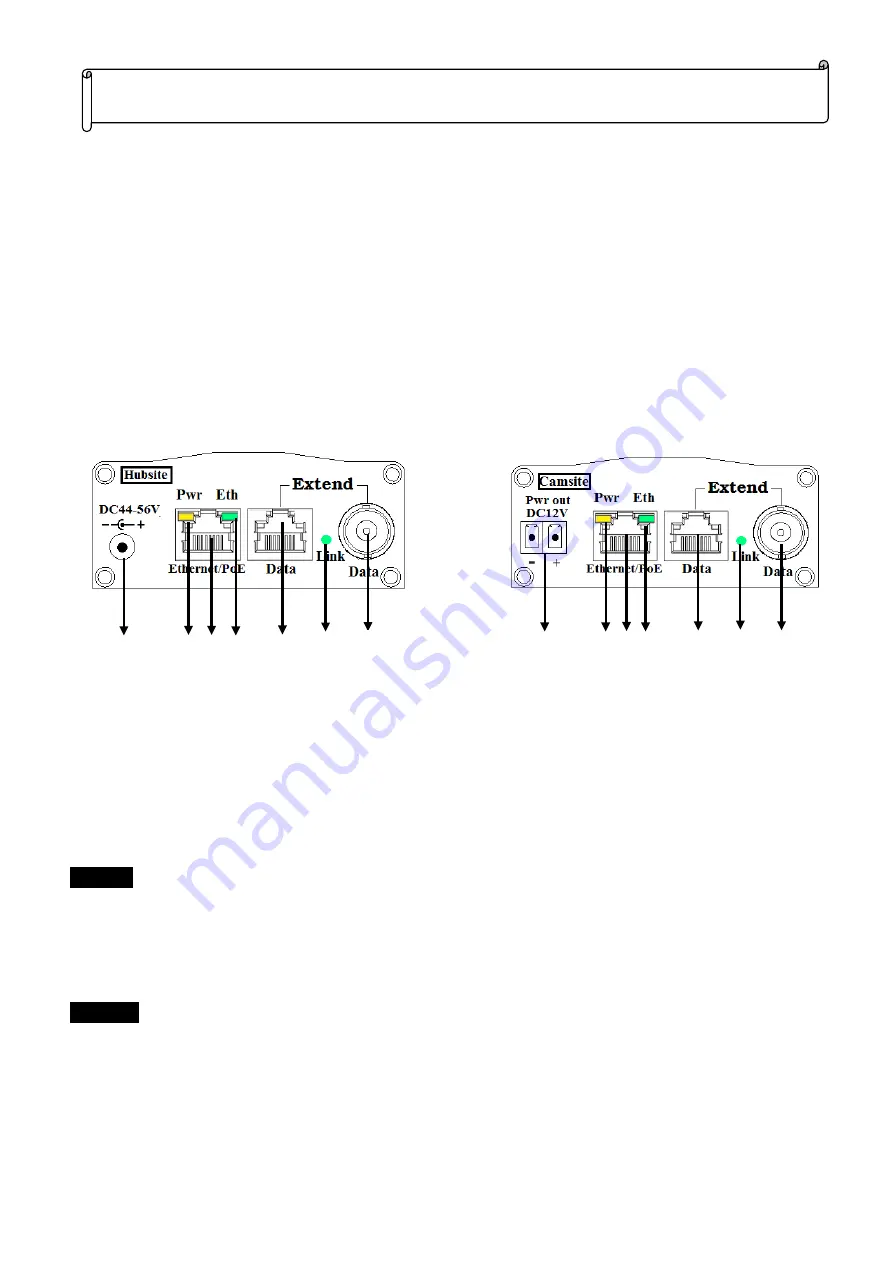
Power jack:
Plug DC48~56V power adapter. (The EPOC-151VA cannot )
2.
Pwr:
The LED indicates the power status. On: Power on; Off: No power.
3.
Ethernet/PoE:
Giga Ethernet RJ45 connector, attaches to Hub, PC or IP Camera via Cat. 5e, 6 or 7 patch
cables.
4.
Eth:
To indicates the Ethernet communication status. Flash: Communicate with Traffic; Off: No connection.
5.
Extend:
RJ45 Female (No LED)/BNC Connector allows 10/100/1000 Base-T Ethernet and PoE power to be
transmitted using Cat. 5e (or better) UTP cable with 4 pair wires or RG59 (or better) Coaxial cable.
6.
Link:
The LED indicates the cable link status. The LED will be on after 10 seconds when first connection is
success; Off: No connection.
7.
Terminal Block:
Support DC12V power output.
Packing Checklist:
Check the package box the following items are included:
EPoC-151VA x1 pc
EoPC-151PS (or EPoC-151HP ) x1 pc
DC power adapter x 1pc
Installation Steps:
Camsite
1.
Connect the Hub or IP camera RJ45 connector to the 10/100/1000 Base-T Ethernet port of EPoC-151PS (or
EPoC-151HP) using a standard Cat 5e (or better) cable of maximum 100 m (328 feet) in length.
2.
Connect one end of the long UTP cable (Cat. 5e or better ) the RJ45 (No light) connector or Coaxial cable (RG59
or better) to BNC connector of EPoC-151PS (or EPoC-151HP).
Hubsite
1.
Connect the Switch Hub RJ45 connector to the 10/100/1000 Base-T Ethernet port of EPoC-151VA using a
standard Cat.5e/6 cable of maximum 100 m (328 feet) in length.
2.
Connect one end of the long UTP cable (Cat. 5e or better ) the RJ45 (No light) connector or Coaxial cable (RG59
or better) to BNC connector of EPoC-151VA.
3.
When the EPoC-151PS (EPoC-151HP) cannot receive power through the Wire cable, please change to DC56V
power adapter to EPoC-151VA. Please refer to “
Power Distance VS. Cable Impedance
” table.
Giga Ethernet/PoE Extender over UTP Cable Installation Guide
V1.3
6
5
4
3
2
1
5
6
4
2
3
7
5
5


