i
5
OIM AI-5X82 V2.1 Page 5 of 6
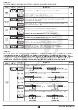
TABLE 4 :
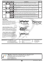
Below listed parameters will appear only, if OUTPUT 2 is selected as ALARM mode. In ALARM mode, controller
continuously compares PV with either SP (For Deviation or Band alarm) or an independent ALARM SP2 (For
process high and process low Alarm). Alarm will occur when PV falls outside the set alarm limits. Also, OP2 will
energize or de-energize under Alarm condition as per the Alarm logic(AL.LG) selected. HYS2 in control List
decides when to switch OFF the alarm. Instrument supports four types of Alarm as described below :-
(Direct acting)
(Direct acting)
OUTPUT-2 ON
OUTPUT-2 OFF
SP2
PV
(Direct acting)
SP2
OUTPUT-2 OFF
OUTPUT-2 ON
PV
(Reverse acting)
OUTPUT-2 OFF
OUTPUT-2 ON
SP2
PV
(Direct acting)
SP2
OUTPUT-2 ON
OUTPUT-2 OFF
PV
(Reverse acting)
(Reverse acting)
(Reverse acting)
OUTPUT ON
SP2
PV
SP1
OUTPUT OFF
OUTPUT ON
OUTPUT ON
PV
SP1
SP2
SP2
OUTPUT OFF
OUTPUT OFF
OUTPUT OFF
PV
SP1
SP2
SP2
OUTPUT ON
OUTPUT OFF
SP2
PV
SP1
OUTPUT ON
PARA
METER
LOWER
DISPLAY
UPPER
DISPLAY
DESCRIPTION
DEFAULT
ALARM
TYPE
DEVIATION
Low Alarm : OP2 activates when PV < SP2.
High Alarm : OP2 activates when PV > SP2.
Deviation Alarm : OP2 activates when PV exceeds SP1
±
set deviation value.
Band Alarm : OP2 activates when PV falls outside the band w.r.t SP1 either direction
TABLE 3 :
Below listed options will appear only, if OP2 is selected as an Auxiliary control mode.
PARA
METER
LOWER
DISPLAY
UPPER
DISPLAY
DESCRIPTION
DEFAULT
INPUT
TYPE
If selected, User can set SP2 value independently, irrespective of SP1.
Abs
In this mode, SP2 is always related with SP1.
User can set SP2 value with deviation of ± 99°C w.r.t SP1.
OUTPUT 2
LOGIC
User can select Heat logic for control Output 2 in which OP2 will remain ON till PV < SP
(PV increases when output is ON)
User can select Cool logic for control Output 2 in which OP2 will remain ON till PV > SP
(PV decreases when output is ON)
Heat
SET
POINT
1
SET
POINT
2
If Enabled, User can view & edit the Set Point (SP1) in USER list.
If Enabled, User can view & edit the Set Point (SP2) in USER list.
If Disabled, User cannot view or edit Set Point (SP1) in USER list.
If Disabled, User cannot view or edit Set Point (SP2) in USER list.
Enable
Enable
USER
LOCK
CODE
Default USER LOCK CODE is 15 to access Control & Configuration List.
User has a choice to set its own USER LOCK CODE between 1 to 9999, this is to
prevent unauthorized access of Control & Configuration List.
15


