background image

Accessing computers using the OSD:   
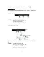
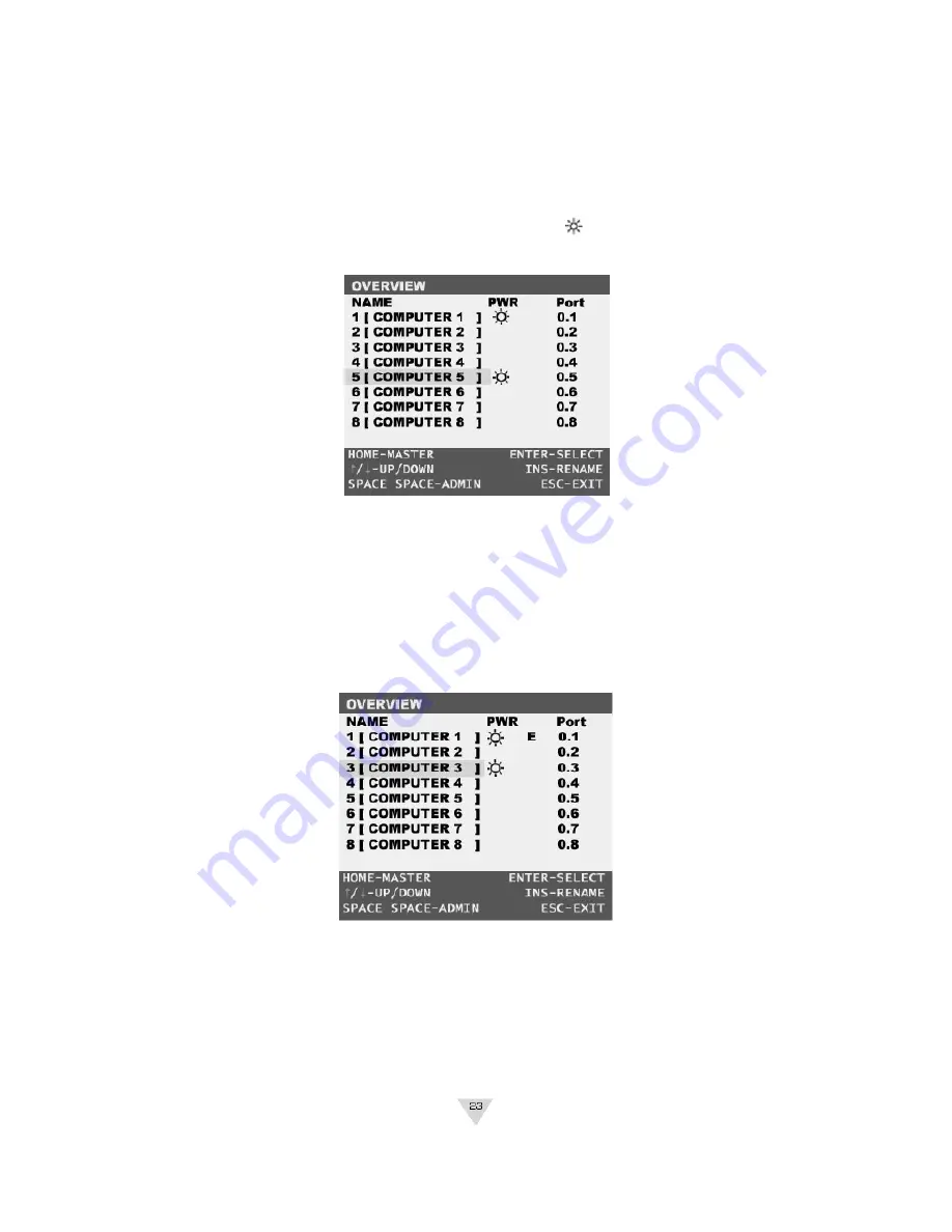
To access computers of the Master Switch   

1.    Invoke the Hot key mode by pressing the [SCROLL LOCK] key twice within two seconds. 


2.    Key in [SPACE] 


3.    Move the highlight bar between 1 and 8. 


4.    Press [ENTER] to gain access to the computer shown with a 

symbol. 


(Note: the OSD display will be dismissed after [ENTER] is pressed.) 


To access computers of the Slave Switch   

1.    Invoke the Hot key mode by pressing the [SCROLL LOCK] key twice within two seconds. 


2.    Key in [SPACE] 


3.    In the OSD of the Master Switch, move the highlight bar to the cascaded port shown with   an  “ E ” 

symbol. 


Summary of Contents for JKP115-801e

Page 1: ...8 16 Port LCD KVM Switch JKP115 801e 117 801e JKP115 1601e 117 1601e LCD Control Console JKP115e 117e User Manual...

Page 2: ......

Page 3: ...TCH INSTALLATION P13 MULTIPLE STAGE CASCADING INSTALLATION P14 CONNECTING EXTERNAL MOUSE P14 OPERATION P17 HOT KEY OPERATION P17 PORT IDENTIFICATION P17 PORT SELECTION P18 QUICK VIEW SCAN MODE P19 PAS...

Page 4: ...Designed for IT professionals the 8 JKP115 801e 117 801e and 16 JKP115 1601e 117 1601e port JKP1 series leverages the power of existing server networks with minimal intrusion Highly efficient it allo...

Page 5: ...electors Push button selectors allow for convenient manual PC selection LCD Bank Display The LCD Bank Display shows bank identification when cascading Quick View Scan The Quick View Scan function allo...

Page 6: ...hen Cascading Quick View Scan for monitoring connected computers Console s mouse port or touch pad can be easily used to control connected computers Password Security lock access to connected servers...

Page 7: ...ensure optimal data transmission our KVM cables feature micro cable construction and are molded together for a neat and organized setup All in one KVM Cable set includes an industry standard coaxial V...

Page 8: ...Note Specifications are subject to change without notice...

Page 9: ...iew 1 Console Drawer Handle 2 LCD Display 15 17 3 LCD Display Control see the LCD Display Guide for details 4 Power Switch 5 LCD Bank Display 6 External Mouse Port 7 Touchpad 8 Mouse Touch Pad Switch...

Page 10: ...617JKP1 Rear View 1 DC Input 2 Firmware Upgrade Port 3 PC Ports...

Page 11: ...event damage to your installation due to ground potential difference make sure that all computers on the installation are properly grounded Failure to follow these instructions can result in damage to...

Page 12: ...cabinet rails Note The slider brackets are extendable to a rack depth of 22 to 36 2 Gently slide the JKP1 chassis into the fixed brackets of the rack rail assembly 3 Fasten the front end bracket screw...

Page 13: ...ntinue to press and button to select function Then press SEL to enter these functions and adjust them to your personal Auto Brightness Contrast Horizontal Vertical Color OSDHP OSDVP OSD Time Language...

Page 14: ...s Contrast Horizontal Vertical Color OSDHP OSDVP OSD Time Language Recall Exit 3 Press the SEL button to enter 4 Use the and button to adjust the brightness of the display 5 Press the SEL button to go...

Page 15: ...l Adjust LCD setting back to previous setting Color OSDHP Adjust OSD horizontal level 0 255 OSDVP Adjust OSD vertical level 0 255 OSD TIME Adjust OSD time 5 60 seconds Language Chinese English Recall...

Page 16: ...rt indicated on the rear of the KVM Switch Connect the other male VGA HDDB 15 cable end to the VGA port of the computer you re installing 3 Connect the PS 2 keyboard and mouse connectors of the KVM ca...

Page 17: ...801e 117 801e and 16 JKP115 1601e 117 1601e additional switches can be cascade from the CPU ports of the First Stage Master switch The cascaded Switches that connect back to the First Stage switch are...

Page 18: ...e the male HDDB 15pin connector and plug it into the PC1 port indicated on the rear of the second stage switch Connect the other male VGA HDDB 15 cable end to the VGA port of the computer you re insta...

Page 19: ...eset confirmation Confirmation Procedure Once all computers are powered on the switch emulates both mouse and keyboard signals on each port allowing your computer to boot normally without errors To ma...

Page 20: ...ed and ready Online The JKP1 series is also equipped with seven segment LCD display for BANK identification when cascading HOT KEYS Port Identification Each computer in a JKP1 installation has a speci...

Page 21: ...ess a PC with the port ID 08 Press SCROLL LOCK SCROLL LOCK 08 To access a PC with the port ID 05 Press SCROLL LOCK SCROLL LOCK 05 Multiple Switch Installation Cascade Note The above working diagram re...

Page 22: ...ndicating that the connected computer is under Auto Scan mode Setting the Quick View Scan Time The scan time or the time the Switch spends on each port can be changed using either Hot Keys or OSD Pass...

Page 23: ...d within 2 seconds 2 The Shift key can be another Hot Key choice 3 You will find that after the KVM unit switches to another computer there is a mouse keyboard delay of 1 2 seconds This is normal and...

Page 24: ...reen is generated by the Switch and does not affect your computers or software in any way OSD Overview Menu The main On Screen Display OSD menu can be accessed by doing the following 1 Press the SCROL...

Page 25: ...port OSD Main Menu Functions This section provides details on the use of the following OSD functions HOME MASTER UP DOWN SPACE ADMIN ENTER INS and ESC From the main OSD mode the following OSD functio...

Page 26: ...ght bar between 1 and 8 4 Press ENTER to gain access to the computer shown with a symbol Note the OSD display will be dismissed after ENTER is pressed To access computers of the Slave Switch 1 Invoke...

Page 27: ...omputer and press ENTER Note the JKP1 series is designed for 2 levels of cascading only Returning to the Master Switch Using OSD 1 Invoke the Hot key mode by pressing the SCROLL LOCK key twice within...

Page 28: ...t OSD menu press ESC OSD Administration Sub Menu This section provides details on configuring default Hot keys to setting up user password access To access the Administration sub menu complete the fol...

Page 29: ...D function setting to default values server names designated by the administrator are NOT affected Perform an OSD Reset when Daisy Chaining or when keyboard mouse inactivity is experienced NOTE Pressi...

Page 30: ...de program by double clicking on the latest firmware file from customer support web site 2 Use a computer that is not connected to your KVM computer ports 3 Connect the power cord to the power jack of...

Page 31: ...gh environmental standards Whether it s in educational government or corporate sectors the JKP115e 117e provides network administrators and IT managers a stable management tool for server access and c...

Page 32: ...ipment If you encounter a problem contact your dealer Please read this manual thoroughly Follow the installation guide and operation procedures carefully to prevent any damage to the JKP115eRM 117e an...

Page 33: ...andle 2 LCD Display 15 17 3 LCD Display Controls 4 External mouse port 5 Touchpad and keyboard 6 Mouse and touch Pad switch 7 Power LED 8 Power Switch 9 Rack mounting Brackets 1 DC input 2 CPU Port Co...

Page 34: ...e RM series includes 2 adjustable sliding rack mount brackets for installation in 19 inch rack systems The sliding brackets feature adjustable positions for rack depths of 22 36 inches Important Infor...

Page 35: ...LCD cover Note The front end screws must be fastened to properly secure the RM chassis to the server rack Installation of JKP115eRM 117e 1 Plug the VGA Mouse Keyboard cable to the JKP115eRM 117e unit...

Page 36: ...ntinue to press and button to select function Then press SEL to enter these functions and adjust them to your personal Auto Brightness Contrast Horizontal Vertical Color OSDHP OSDVP OSD Time Language...

Page 37: ...s Contrast Horizontal Vertical Color OSDHP OSDVP OSD Time Language Recall Exit 3 Press the SEL button to enter 4 Use the and button to adjust the brightness of the display 5 Press the SEL button to go...

Page 38: ...l Adjust LCD setting back to previous setting Color OSDHP Adjust OSD horizontal level 0 255 OSDVP Adjust OSD vertical level 0 255 OSD TIME Adjust OSD time 5 60 seconds Language Chinese English Recall...

Page 39: ...ing measures Reorient or relocate the receiving antenna Increase the separation between the equipment and receiver Connect the equipment into an outlet on a circuit different from that to which the re...

Reviews: