background image

10

Step 3

When the SUPER-D6 function is set to "OFF", bright areas of an image are masked to facilitate the visibility of dark areas. 
Move the cursor to “MASK SET” and press the [SET] button.

→ 

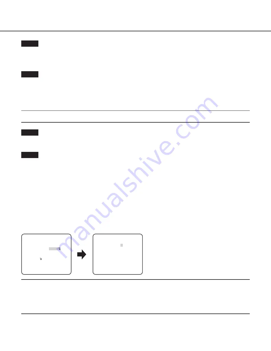
The mask setting screen appears. 

Step 4

Press the [UP], [DOWN], [RIGHT] and [LEFT] buttons to move the flashing cursor to the area to be masked and press the [SET] 
button. 
When the selected area is masked, the masked area will start blinking (between stripes and white). When the flashing cursor is moved 
to other areas, the masked area will be displayed in white. 
Repeat the above procedure to mask other areas as necessary.

Note:

  •  To cancel the masking, select the masked area to be canceled, and then press the [SET] button. The masked area will be deleted.

Step 5

Hold down the [SET] button for more than 2 seconds after completion of masking.

 Return to the previous menu.

Step 6

Move the cursor to “LEVEL” and press the [RIGHT] or [LEFT] button to adjust the level. 

About the highlight compensation (HLC) function

This function is a backlight compensation technology that enables the camera to obtain clear images in a strong light environment. 
When “SUPER-D6” is set to “ON”, this function cannot be set. 
Available options: ON (1)/ON (2)/OFF
ON (1):  When the camera faces the light source, this function can be used to block strong light so as to reduce over exposure as 

much as possible and retain lots of screen details. 

The mask area has three options: small (S), medium (M) and large (L), which are used to adjust the area of the mask zone. 
When the mask level cursor moves towards the “+” direction, the mask color becomes pale; when the mask level cursor moves towards 
the “-” direction, the mask color becomes dark. 

ON (2):  When the camera faces the light source, strong light can be effectively suppressed and screen details can be retained to the 

maximum extent. 

“ALC CONT” screen

**ALC CONT**(1)
BACK LIGHT COMP 

OFF

MASK SET


-     +

LEVEL        .I.....   0

 RET TOP END

SUPER-D6

FOG COMP   


---

   ON

(1)    

HLC

HLC setting screen

**HLC**(1)

S


-     +

..I....2 

 RET TOP END

AREA 
MASK LEVEL  

Note:

  •  According to different highlight parts on the screen, different HLC functions may be provided. 
  •  The HLC function can be enabled only when the brightness area exceeds the normal specification. 
  •  When the HLC function is set to “ON (1)” or “ON (2)”, “FOG COMP” is displayed as “---” and the fog compensation function can-

not be set. 

  •  After “SUPER-D6” switches from “ON” to “OFF”, “HLC” and “FOG COMP” are displayed as “OFF”.

Summary of Contents for WV-CW630G

Page 1: ...ase read these instructions carefully and save this manual for future use The model number is abbreviated in some descriptions in this manual Operating Instructions Color CCTV Camera Model No WV CW630...

Page 2: ...he installation guide for further information about how to install the camera Adobe Reader is required to read PDF When the Adobe Reader is not installed on the PC download the latest Adobe Reader fro...

Page 3: ...13 7 Digital noise reduction function setting DNR 13 8 Black and white mode setting D N IR 14 9 VMD setting VMD 15 Setting of motion detection 15 Setting of scene change detection 17 Camera system se...

Page 4: ...m such as synchronization and privacy zone SYNC Only INT method can be used PRIVACY ZONE Hides undesired portions in the camera shooting area STABILIZER Decides whether or not to enable the image stab...

Page 5: ...ACK FOCUS Screenshot 3 The selected setup screen in the setup menu appears on the screen Note If the top screen of the setup menu is called up with the SET button while the camera is operated the setu...

Page 6: ...TOP END RESET SYSTEM SETUP SYNC INT PRIVACY ZONE OFF STABILIZER OFF EL ZOOM OFF UPSIDE DOWN OFF LDC I 0 RET TOP END SPECIAL SETUP CHROMA GAIN I 160 AP GAIN I 20 PEDESTAL I 32 PIX OFF DISPLAY ALARM CA...

Page 7: ...er The entered characters are displayed in the editing area Character entry To revise a character move the arrow in the editing area to a wrong character with use of the RIGHT or LEFT button and enter...

Page 8: ...CENE1 to resume normal operation 2 Light quantity control method selection ALC ELC The method of controlling the quantity of light is selected from the following in accordance with the lens to be used...

Page 9: ...NT screen appears Note When ALC ELC is set to ELC or ALC and the SET button is pressed the ELC CONT or ALC CONT screen will appear When ELC or ALC is selected the SUPER D6 function is disabled appears...

Page 10: ...strong light environment When SUPER D6 is set to ON this function cannot be set Available options ON 1 ON 2 OFF ON 1 When the camera faces the light source this function can be used to block strong l...

Page 11: ...hutter function cannot be activated 4 Gain control setting AGC Select a gain control setting from the following ON HIGH default ON MID ON LOW Automatically increases the gain to make the screen bright...

Page 12: ...of the color temperature ranges from 2000 K to 10000 K When AWC is selected the white balance needs to be adjusted Note If the situation meets one of the followings color may not be accurately reprod...

Page 13: ...on the color becomes deeper and when the level indicator moves in the direction the color becomes lighter Step 3 Move the cursor to AREA and press the SET button to enter AREA setting screen The area...

Page 14: ...merely determined by information from the CCD image sensor When AUTO2 is selected the wave length of the light source shall be 800 nm or longer Step 2 Press the SET button The D N IR screen appears S...

Page 15: ...for example when shooting at night The subject is moving straight at the camera The subject is moving too fast or too slow The subject is too small or too large There are too many moving objects Light...

Page 16: ...e previous menu Step 4 Move the cursor to ALARM and press the RIGHT and LEFT buttons to select ON or OFF ON Outputs alarm signal when in display mode Actions may be confirmed through the motion detect...

Page 17: ...a change in the subject state that occurs by covering the camera with a cloth a cap or others or by changing the camera direction largely Follow the procedure below CAMERA SETUP screen VMD SCENE CHANG...

Page 18: ...the procedure below to set the privacy zone Note The privacy zone function is disabled at initializing the unit i e right after turning on the power SYSTEM SETUP screen ZONE NUMBER screen ON 2 SYSTEM...

Page 19: ...is selected for the image stabilizer check the view angle and resolution at camera installation The image stabilizer function may not work for the following subjects or conditions Dark subject Less c...

Page 20: ...area to be set and press the SET button The position can be changed in the range of zoom factor set in the zoom setting screen 14 Upside down setting UPSIDE DOWN ON The video image can be reversed up...

Page 21: ...e back focus move the cursor to MANUAL ADJ press the SET button and use the RIGHT or LEFT button to adjust the back focus manually Note BACK FOCUS SETUP screen BACK FOCUS SETUP ABF PUSH SET MANUAL ADJ...

Page 22: ...CK and selecting ON allow users to disable the back focus adjustment with the operation buttons default OFF Important The following are recommendation for back focus setting in accordance with subject...

Page 23: ...iew a video monitor when the adjustment is performed Note Moire interference fringes may be observed when shooting a subject with fine pattern such as a carpet or a curtain In such a case move the ind...

Page 24: ...sterisk is attached at the right side of the number when registration is completed The coordinate is expressed in figures Note To clear the registered pixel compensation point move the cursor to 1 of...

Page 25: ...all up the screen Move the cursor to LANGUAGE and press the RIGHT or LEFT button to select the target language then move the cursor to SET and press the SET button Select the target language from the...

Page 26: ...function Electronic shutter speed 1 step slower 1 7 5 Camera function Gain adjustment AGC ON 1 7 6 Camera function Gain adjustment AGC OFF 1 7 7 Camera function Electronic sensitivity up SENS UP FIX...

Page 27: ...GQP2098VA i PRO Co Ltd Fukuoka Japan https www i pro com Authorised Representative in EU i PRO EMEA B V Laarderhoogtweg 25 1101 EB Amsterdam Netherlands i PRO EMEA B V UK Branch 1010 Cambourne Busines...

Reviews: