15
Major operating controls and their functions
(continued)
⑭
Power cord inlet [AC IN]
Connect the included power cord to this inlet.
⑮
[POWER] switch
Press it to turn on the power. Press it again to turn off
the power.
Important:
• Turn on the power of all extension units first if
connected, and then turn on the power of the recorder.
• Turn off the power of the recorder first when turning off
the power.
⑯
SIGNAL GND terminal [SIGNAL GND]
Connect this terminal with the SIGNAL GND terminals of
the devices in the system for signal ground. When
operating the recorder and the devices in the system
without signal ground, noise may be produced.
⑰
Cooling fan outlet
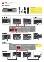
How to fix the power cord
Fix the power cord at 15 cm to 20 cm {5-7/8 to 7-7/8 inches}
from the connector with the included power cord clamp
passed through the clamp mount.
Fix the power cord so that it does not block the cooling fan
outlet.
⋇
⋈
Clamp mount
Power cord clamp
①
Pass the power cord clamp through the clamp mount.
②
Make a ring with the power cord clamp as shown in
the illustration to tighten the power cord.
⋉
15 cm to 20 cm
{5-7/8 to 7-7/8 inches}
③
Tighten the power cord at 15 cm to 20 cm {5-7/8 to
7-7/8 inches} from the connector and fix it to the
clamp mount.
Cut the unnecessary part of the power cord clamp as
necessary.
How to fix the USB cable
Fix the USB cable with the included power cord clamp
passed through the slot on either the top or bottom of the
clamp mount (for fixing USB cable) as shown below.
Cut the unnecessary part of the power cord clamp as
necessary.
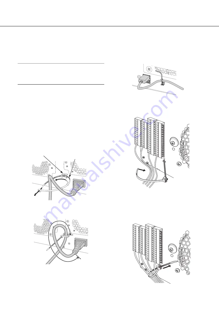
Fitting of the cable clamp (for
fixing the terminal block cables)
⋇
⋈
①
Insert the (included) cable clamp into the cable clamp
fitting hole.
②
Tie cables of the ALARM/CONTROL terminals and of
the ALARM IN terminal with the cable tie of the cable
clamp (included).
Tie the cables to the downward-right so that they do
not block the network port.
⋉
③
Fasten the cable tie of the cable clamp (included) and
fix it to the upward-right.