Hardware User’s Guide
Installation
9
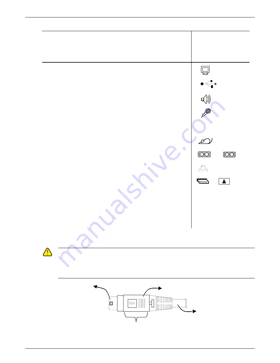
Follow the instructions below to connect various
accessories
Connector Symbol
(see figure 2 – page 8
for the location of
connectors on the rear
panel )
9
Connect the video cable from your display unit to the video port
9
Connect USB devices to the USB ports
9
Connect external speakers to the 16-Bit stereo output port
9
Connect your microphone to the Microphone input port
9
Connect your keyboard to the PS/2 Keyboard port
9
Connect your mouse to the PS/2 Mouse port
9
Connect your serial devices (
E.g Modem
) to the COM ports
or
9
Connect your printer to the parallel port
9
Optional
: Insert the PC-Card (Type I, II or III) into the PC-Card slot
as described below:
1. Align the arrow-mark on the PC Card with the arrow-mark
adjacent to the PC-Card slot on the rear-panel of the client
2. Push the PC-Card into the slot until you feel the card latching
on to the connector
3. Connect one end of a PC-Card cable / dongle to the connector
on the PC-Card and the other end to the external source. The
client is now ready to use the PC-Card
9
Connect the output of the AC-DC Adapter to the inlet of the unit. There will be an audible click
indicating that the plug is securely in place.
C
AUTION
: E
NSURE THAT THE SCREWS PROVIDED WITH
D-
TYPE CONNECTORS
(COM1, COM2, V
IDEO
,
AND
P
ARALLEL PORTS
)
ARE FASTENED
.
C
AUTION
: I
F FOR ANY REASON
,
YOU WANT TO DISCONNECT THE POWER
-
CORD CONNECTED TO THE
UNIT
,
HOLD ONLY THE
SPRING
-
LOADED SHROUD
(
SEE FIGURE
3
)
WHILE PULLING OUT THE CONNECTOR
;
D
O NOT HOLD THE POWER
-
CORD ITSELF
.
1
2
Hold here while disconnecting
the power cord
Cord
Spring-loaded shroud
Connector
Figure 3
Summary of Contents for I-O TC4000 Series
Page 1: ...1 Hardware User s Guide...


