26
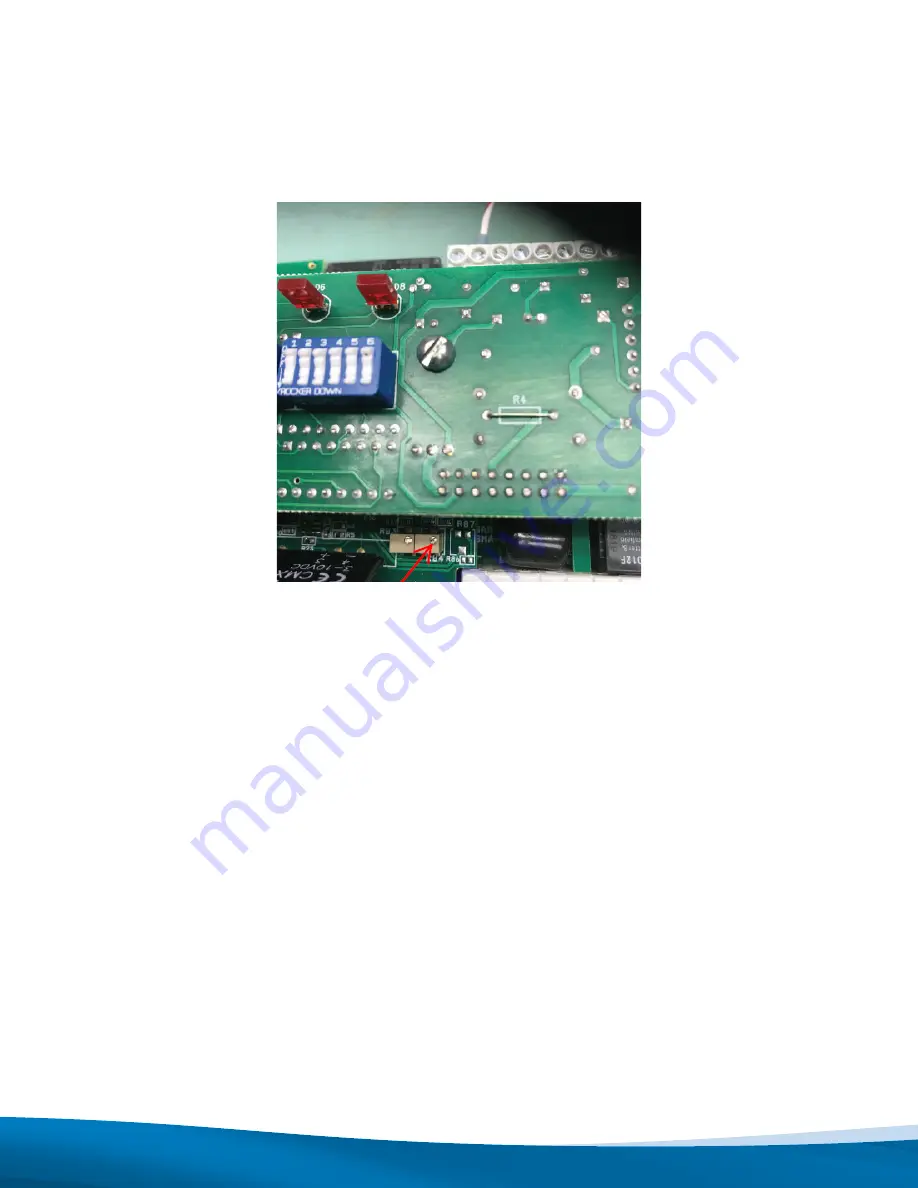
4.3 Locate potentiometer R84 as shown in the Figure 10.1 below.
4.4 With control power still provided to the Sigma3, adjust the potentiometer until the HF1 current is 19mA.
5. Offline Calibration Procedure
1. Make note of the present Sigma3 DIP switch settings.
2. De-energize the system (i.e. ensure the NGR associated with this Sigma3 is not live).
3. Install (if not present already) a DC micro ammeter (scaled 0-1mA : 0-100%) to terminals 49 and 50 of the
Sigma3 as shown in Figure 10.2 below.
4. Set DIP switch 14 and 15 to ON with the rest of the DIP switches set to OFF.
5. Wait for the FUNC LED to clear.
6. Press RESET.
7. Enter calibration mode by pressing TEST and RESET at the same time. Ensure that the LEDs are not on at the
moment that calibration mode is initiated.
8. Short part of the NGR out so that it has an impedance of 10% of the NGR ohmic value (e.g. if the NGR has a rating
of 55Ω, short out enough elements of the NGR to give an impedance of approximately 5Ω. See Figure 10.3 below.
If the NGR has a pulsing section, ensure that the short includes the pulsing section.
Figure 10.1: Potentiometer to be used to Adjust HF1 Current


