background image

0-8

TEMPERATURE

TEMPERATURE

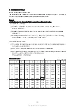
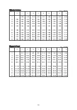
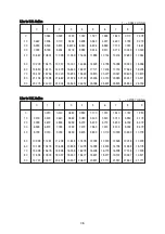
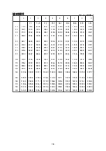
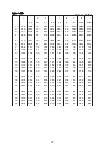
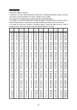
Fahrenheit-Centigrade Conversion.  
A simple way to convert a fahrenheit temperature reading into a centigrade temperature reading or vice verse 
is to enter the accompanying table in the center or boldface column of figures.
These figures refer to the temperature in either Fahrenheit or Centigrade degrees.
If it is desired to convert from Fahrenheit to Centigrade degrees, consider the center column as a table of 
Fahrenheit temperatures and read the corresponding Centigrade temperature in the column at the left.
If it is desired to convert from Centigrade to Fahrenheit degrees, consider the center column as a table of 
Centigrade values, and read the corresponding Fahrenheit temperature on the right.


˚C


˚F


˚C


˚F


˚C


˚F


˚C


˚F

 -40.4 

-40 

-40.0 

-11.7 

11 

51.8 

7.8 

46 

114.8 

27.2 

81 

117.8

 -37.2 

-35 

-31.0 

-11.1 

12 

53.6 

8.3 

47 

116.6 

27.8 

82 

179.6

 -34.4 

-30 

-22.0 

-10.6 

13 

55.4 

8.9 

48 

118.4 

28.3 

83 

181.4

 -31.7 

-25 

-13.0 

-10.0 

14 

57.2 

9.4 

49 

120.2 

28.9 

84 

183.2

 -28.9 

-20 

-4.0 

-9.4 

15 

59.0 

10.0 

50 

122.0 

29.4 

85 

185.0

 -28.3 

-19 

-2.2 

-8.9 

16 

60.8 

10.6 

51 

123.8 

30.0 

86 

186.8

 -27.8 

-18 

-0.4 

-8.3 

17 

62.6 

11.1 

52 

125.6 

30.6 

87 

188.6

 -27.2 

-17 

1.4 

-7.8 

18 

64.4 

11.7 

53 

127.4 

31.1 

88 

190.4

 -26.7 

-16 

3.2 

-6.7 

20 

68.0 

12.8 

55 

131.0 

32.2 

90 

194.0

 -26.1 

-15 

5.0 

-6.7 

20 

68.0 

12.8 

55 

131.0 

32.2 

90 

194.0

 -25.6 

-14 

6.8 

-6.1 

21 

69.8 

13.3 

56 

132.8 

32.8 

91 

195.8

 -25.0 

-13 

8.6 

-5.6 

22 

71.6 

13.9 

57 

134.6 

33.3 

92 

197.6

 -24.4 

-12 

10.4 

-5.0 

23 

73.4 

14.4 

58 

136.4 

33.9 

93 

199.4

 -23.9 

-11 

12.2 

-4.4 

24 

75.2 

15.0 

59 

138.2 

34.4 

94 

201.2

 -23.3 

-10 

14.0 

-3.9 

25 

77.0 

15.6 

60 

140.0 

35.0 

95 

203.0

 -22.8 

-9 

15.8 

-3.3 

26 

78.8 

16.1 

61 

141.8 

35.6 

96 

204.8

 -22.2 

-8 

17.6 

-2.8 

27 

80.6 

16.7 

62 

143.6 

36.1 

97 

206.6

 -21.7 

-7 

19.4 

-2.2 

28 

82.4 

17.2 

63 

145.4 

36.7 

98 

208.4

 -21.1 

-6 

21.2 

-1.7 

29 

84.2 

17.8 

64 

147.2 

37.2 

99 

210.2

 -20.6 

-5 

23.0 

-1.1 

35 

95.0 

21.1 

70 

158.0 

51.7 

125 

257.0

 -20.0 

-4 

24.8 

-0.6 

31 

87.8 

18.9 

66 

150.8 

40.6 

105 

221.0

 -19.4 

-3 

26.6 

32 

89.6 

19.4 

67 

152.6 

43.3 

110 

230.0

 -18.9 

-2 

28.4 

0.6 

33 

91.4 

20.0 

68 

154.4 

46.1 

115 

239.0

 -18.3 

-1 

30.2 

1.1 

34 

93.2 

20.6 

69 

156.2 

48.9 

120 

248.0

 -17.8 

32.0 

1.7 

35 

95.0 

21.1 

70 

158.0 

51.7 

125 

257.0

 -17.2 

33.8 

2.2 

36 

96.8 

21.7 

71 

159.8 

54.4 

130 

266.0

 -16.7 

35.6 

2.8 

37 

98.6 

22.2 

72 

161.6 

57.2 

135 

275.0

 -16.1 

37.4 

3.3 

38 

100.4 

22.8 

73 

163.4 

60.0 

140 

284.0

 -15.6 

39.2 

3.9 

39 

102.2 

23.3 

74 

165.2 

62.7 

145 

293.0

 -15.0 

41.0 

4.4 

40 

104.0 

23.9 

75 

167.0 

65.6 

150 

302.0

 -14.4 

42.8 

5.0 

41 

105.8 

24.4 

76 

168.8 

68.3 

155 

311.0

 -13.9 

44.6 

5.6 

42 

107.6 

25.0 

77 

170.6 

71.1 

160 

320.0

 -13.3 

46.4 

6.1 

43 

109.4 

25.6 

78 

172.4 

73.9 

165 

329.0

 -12.8 

48.2 

6.7 

44 

111.2 

26.1 

79 

174.2 

76.7 

170 

338.0

 -12.2 

10 

50.0 

7.2 

45 

113.0 

26.7 

80 

176.0 

79.4 

172 

347.0

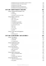
Summary of Contents for Robex 290LC-9

Page 1: ...Robex 290LC 9 CRAWLER EXCAVATOR SERVICE MANUAL...

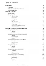
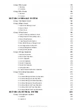
Page 2: ...ON 2 STRUCTURE AND FUNCTION 56 Group 1 Pump Device 57 1 Structure 57 2 Function 63 Group 2 Main Control Valve 0163 And Up 76 1 Structure 76 2 Hydraulic Circuit 82 3 Function 83 Group 2 Main Control Va...

Page 3: ...03 8 Swing Priority System 204 Group 4 Single Operation 205 1 Boom Up Operation 205 2 Boom Down Operation 206 3 Arm In Operation 207 4 Arm Out Operation 208 5 Bucket In Operation 209 6 Bucket Out Oper...

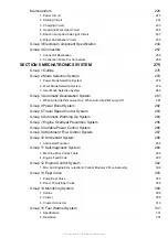
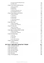
Page 4: ...uto Idle Pilot Lamp Off 281 Group 4 Power Boost System 282 Group 5 Travel Speed Control System 283 Group 6 Automatic Warming Up System 284 Group 7 Engine Overheat Prevention System 285 Group 8 Variabl...

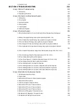
Page 5: ...r 4 363 9 When Fuel Gauge Does Not Operate hcespn 301 Fmi 3 Or 4 364 10 When Safety Solenoid Does Not Operate 365 11 When Travel Speed 1 2 Does Not Operate hcespn 167 Fmi 5 Or 6 366 12 When Engine Doe...

Page 6: ...vel Motor 0307 And Up 428 5 Travel Reduction Gear 429 6 Rcv Lever 430 7 Rcv Pedal 431 8 Turning Joint 432 9 Cylinder 433 Group 3 Track And Work Equipment 434 1 Track 434 2 Work Equipment 439 SECTION 8...

Page 7: ...Disassembly And Assembly 580 Group 8 Turning Joint 593 1 Removal And Install 593 2 Disassembly And Assembly 594 Group 9 Boom Arm And Bucket Cylinder 598 1 Removal And Install 598 2 Disassembly And Ass...

Page 8: ...EM SECTION 4 ELECTRICAL SYSTEM This section explains the electrical circuit monitoring system and each component It serves not only to give an understanding electrical system but also serves as refere...

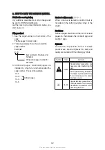
Page 9: ...t up to date information before you start any work Filing method Filing method See the page number on the bottom of the page File the pages in correct order Following examples shows how to read the pa...

Page 10: ...ove the decimal point one place to the left to convert it to 55mm Carry out the same procedure as above to convert 55mm to 2 165 inches The original value 550mm was divided by 10 so multiply 2 165 inc...

Page 11: ...3 425 3 465 3 504 90 3 543 3 583 3 622 3 661 3 701 3 740 3 780 3 819 3 858 3 898 Kilogram to Pound Kilogram to Pound 1kg 2 2046lb 0 1 2 3 4 5 6 7 8 9 0 2 20 4 41 6 61 8 82 11 02 13 23 15 43 17 64 19...

Page 12: ...455 22 719 22 983 23 247 23 511 90 23 775 24 040 24 304 24 568 24 832 25 096 25 631 25 625 25 889 26 153 Liter to U K Gallon Liter to U K Gallon 1 0 21997 U K Gal 0 1 2 3 4 5 6 7 8 9 0 0 220 0 440 0...

Page 13: ...8 622 0 629 3 636 5 643 7 90 651 0 658 2 665 4 672 7 679 9 687 1 694 4 701 6 708 8 716 1 100 723 3 730 5 737 8 745 0 752 2 759 5 766 7 773 9 781 2 788 4 110 795 6 802 9 810 1 817 3 824 6 831 8 839 0 8...

Page 14: ...266 90 1280 1294 1309 1323 1337 1351 1365 1380 1394 1408 100 1422 1437 1451 1465 1479 1493 1508 1522 1536 1550 110 1565 1579 1593 1607 1621 1636 1650 1664 1678 1693 120 1707 1721 1735 1749 1764 1778 1...

Page 15: ...1 0 32 2 90 194 0 26 1 15 5 0 6 7 20 68 0 12 8 55 131 0 32 2 90 194 0 25 6 14 6 8 6 1 21 69 8 13 3 56 132 8 32 8 91 195 8 25 0 13 8 6 5 6 22 71 6 13 9 57 134 6 33 3 92 197 6 24 4 12 10 4 5 0 23 73 4 1...

Page 16: ...SECTION 1 GENERAL SECTION 1 GENERAL Group 1 Safety Hints 1 1 Group 2 Specifications 1 10...

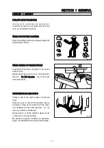
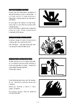
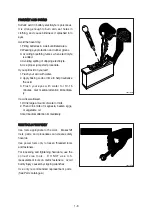
Page 17: ...e excavator attach a Do Not Operate Do Not Operate tag on the right side control lever USE HANDHOLDS AND STEPS USE HANDHOLDS AND STEPS Falling is one of the major causes of personal injury When you ge...

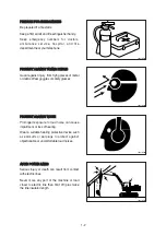
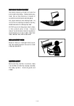
Page 18: ...Wear goggles or safety glasses PROTECT AGAINST NOISE PROTECT AGAINST NOISE Prolonged exposure to loud noise can cause impairment or loss of hearing Wear a suitable hearing protective device such as e...

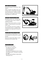
Page 19: ...vator starts to move Use a signal person when moving swinging or operating the machine in congested areas Coordinate hand signals before starting the excavator OPERATE ONLY FORM OPERATOR S SEAT OPERAT...

Page 20: ...YSTEM SAFELY Explosive release of fluids from pressurized cooling system can cause serious burns Shut off engine Only remove filler cap when cool enough to touch with bare hands HANDLE FLUIDS SAFELY A...

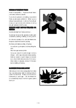
Page 21: ...ide or in a well ventilated area Dispose of paint and solvent properly Remove paint before welding or heating If you sand or grind paint avoid breathing the dust Wear an approved respirator If you use...

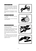
Page 22: ...serious injury To prevent accidents use care when working around rotating parts AVOID HIGH PRESSURE FLUIDS AVOID HIGH PRESSURE FLUIDS Escaping fluid under pressure can penetrate the skin causing serio...

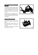
Page 23: ...e materials Pressurized lines can be accidentally cut when heat goes beyond the immediate flame area Install fire resisting guards to protect hoses or other materials PREVENT BATTERY EXPLOSIONS PREVEN...

Page 24: ...lime to help neutralize the acid 3 Flush your eyes with water for 10 15 minutes Get medical attention immediate ly If acid is swallowed 1 Drink large amounts of water or milk 2 Then drink milk of mag...

Page 25: ...m DO NOT pour oil into the ground down a drain or into a stream pond or lake Observe relevant environmental protection regulations when disposing of oil fuel coolant brake fluid filters batteries and...

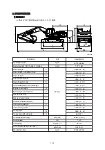
Page 26: ...el tank Battery box Engine Radiator Turning joint Oil cooler Main control valve Swing motor Bucket Tooth Cab Boom cylinder Boom Arm cylinder Arm Muffler Counterweight Bucket cylinder Side cutter Conne...

Page 27: ...length Undercarriage width Track gauge Track shoe width standard Travel speed low high Swing speed Gradeability Ground pressure 600 mm shoe Max traction force km hr mph rpm Degree kgf cm2 psi kg lb 2...

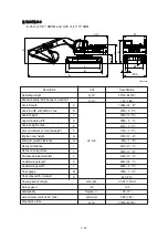
Page 28: ...age width Track gauge Track shoe width standard Travel speed low high Swing speed Gradeability Ground pressure 600 mm shoe Max traction force km hr mph rpm Degree kgf cm2 psi kg lb 29100 64150 1 27 1...

Page 29: ...width standard Travel speed low high Swing speed Gradeability Ground pressure 800 mm shoe Max traction force kg lb m3 yd3 km hr mph rpm Degree kgf cm2 psi kg lb 32690 72630 0 52 0 68 14550 47 9 3400...

Page 30: ...width standard Travel speed low high Swing speed Gradeability Ground pressure 600 mm shoe Max traction force kg lb m3 yd3 mm ft in km hr mph rpm Degree kgf cm2 psi kg lb 32140 70860 1 27 1 66 10430 34...

Page 31: ...19 2 33 2 23 1 13 12 3 05 m 10 0 Arm 10820 mm 10620 mm 7390 mm 7300 mm 6380 mm 10160 mm 7110 mm 4230 mm 35 6 34 10 24 3 23 11 20 11 33 4 23 4 13 11 166 7 181 17000 18460 37480 40690 189 3 205 5 19300...

Page 32: ...eight Min swing radius Bucket digging force Arm crowd force Description 7 85 m 25 9 Arm A A B B C D E F 18510 60 9 18400 60 4 14820 48 7 14690 48 2 12020 39 5 14500 47 7 12190 39 12 6250 20 6 SAE ISO...

Page 33: ...33 7 32 10 21 5 20 9 18 3 33 6 23 6 14 0 3 05 m 10 0 Arm 10790 mm 10530 mm 7090 mm 6910 mm 6090 mm 10440 mm 7400 mm 4230 mm 35 5 34 7 23 3 22 8 20 0 34 3 24 3 13 11 166 7 181 17000 18460 37480 40690 1...

Page 34: ...ndard triple grouser shoe Front attachment assembly 6 25 m boom 3 05 m arm 1 27 m3 SAE heaped bucket 6 25 m boom assembly 3 05 m arm assembly 1 27 m3 SAE heaped bucket Boom cylinder assembly Arm cylin...

Page 35: ...ump assembly Main control valve assembly Swing motor assembly Hydraulic oil tank assembly Fuel tank assembly Counterweight Cab assembly Lower chassis assembly Track frame weld assembly Swing bearing T...

Page 36: ...n pump assembly Main control valve assembly Swing motor assembly Hydraulic oil tank assembly Fuel tank assembly Counterweight Cab assembly Lower chassis assembly Track frame weld assembly Swing bearin...

Page 37: ...50 4240 5970 3590 8 57 5 ft lb 29700 29700 30360 20530 22290 13050 15760 9350 13160 7910 28 1 3 0 m kg 17570 17570 12710 9480 9440 6020 6180 4610 7 47 10 ft lb 38740 38740 28020 20900 20810 13270 1362...

Page 38: ...boom 3 05 m 10 0 arm equipped with 1 27 m3 SAE heaped bucket and 600 mm 24 triple grouser shoe and 5200 kg counterweight 3 Load point height Load radius At max reach 1 5 m 5 ft 3 0 m 10 ft 4 5 m 15 f...

Page 39: ...10 5070 36 2 1 5 m kg 9980 9980 11050 10090 7850 6420 6300 4470 5440 3240 3920 2260 10 97 5 ft lb 22000 22000 24360 22240 17310 14150 13890 9850 11990 7140 8640 4980 36 0 1 5 m kg 9310 9310 12760 1276...

Page 40: ...ft lb 29700 29700 30360 18170 22290 11620 15670 8330 13070 7080 28 1 3 0 m kg 17570 17290 12710 8410 9440 5370 6180 4130 7 47 10 ft lb 38740 38120 28020 18540 20810 11840 13620 9110 24 5 4 5 m kg 141...

Page 41: ...This as a preview PDF file from best manuals com Download full PDF manual at best manuals com...

Reviews: