2. INSTRUCTIONS FOR USE
2.1
Remove from the packaging and make sure that the unit Is not damaged in any way. If
it is damaged report damage immediately and DO NOT use machine.
2.2
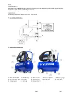
Fit air filter by first removing transit plug - then screw supplied air filter into
compressor - Item 7 on component location chapter 9.
2.3
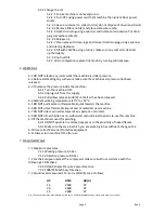
Check the oil level gauge (1) If oil level Is low then carry out the following procedure
to top up oil;
2.3.1
.1 Ideal level shown
2.3.2
.2 Turn OFF using power switch (3) machine then isolate from power source.
2.3.3
.3 Remove filler knob (2) and place somewhere safe.
2.3.4
.4 Fill with 15W 40 using a funnel, make sure that any spilt oil Is cleaned
up thoroughly.
2.3.5
.5 Do not overfill
2.3.6
.6 On completion replace filler knob by turning clockwise.
2.4
Turning machine ON/OFF see power switch (3).
2.4.1
.1 RED knob shown will turn unit 'ON' when pulled upwards.
2.4.2
.2 When RED knob is pressed down the unit will tum 'OFF'.
3. START UP PROCEDURE
3.1
Make sure unit is turned OFF.
3.1.1
Turn machine OFF see power switch (3).
3.1.2
Make sure the RED knob is pressed down which will turn the machine 'OFF'.
3.1.3
Connect machine to suitable supply.
3.2
The machine operation after this point is fully automatic.
3.3
Before starting work leave the compressor running for a few minutes to allow
the machine to warm up the lubricating parts inside compressor.
3.4
The Machine motor will run if the in-built pressure switch is activated.
3.4.1
The pressure switch will work automatically, turning the machine ON as
the pressure falls due to work.
3.4.2
The pressure switch will work automatically, turning the machine OFF
as the pressure inside the tank reaches the maximum limit.
3.5
The machine is protected by a thermal trip and will operate if the machine becomes
overheated. It will restart once machine has cooled this will typically be 15 to 20 minutes.
4. USING THE MACHINE
4.1
Adjusting the working pressure is achieved by adjusting the RED knurled knob (4). The
pressure gauge/s will indicate pressure/s required. The pressures gauge/s are Indicated as
shown (5a & 5b)
4.2
Releasing air pressure from the outlet line is achieved by pulling the Brass release
knob as shown (6).
5. MAINTENANCE
5.1
Check oil level weekly.
5.2
Every 50 hours;
5.2.1
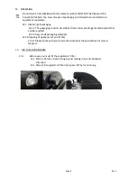
Remove air filter (7) and clean;
5.2.1.1
To remove air filter undo the wing nut by rotating anti-clockwise.
5.2.1.2
Remove cover.
5.2.1.3
Remove filter and clean, make sure the filter is dry before
replacing it into filter housing
5.2.1.4
To replace reverse procedure.
Page 4
Rev 5

