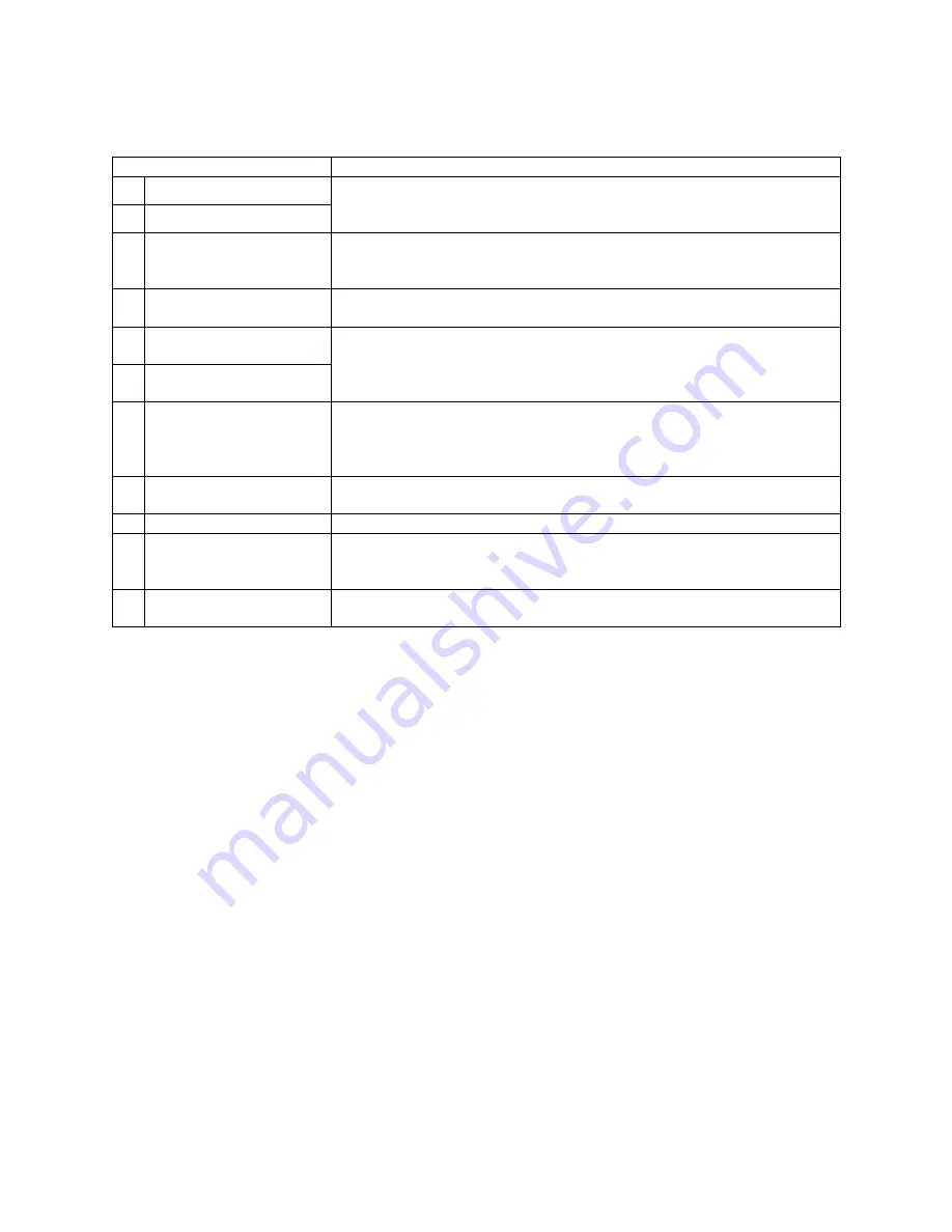
Hyundai H-LCD3200 Instruction Manual Download Page 7

7

Items

Connection description

1  HDMI 

2

2  HDMI 

1

Connect one end of the HDMI cable with HDMI output port, connect the
other end of the HDMI cable with the HDMI port on the TV, and tighten the
bolts clockwise on the each end of HDMI cable.

3 VGA

Connect one end of the VGA cable with the VGA port on computer, con-
nect the other end of the VGA cable with the VGA port on the TV, and
tighten the bolts clockwise on the each end of VGA cable.

4 S-Video

The output S-Video terminal of DVD can be connected with the S-Video
input port of the TV through S-Video cable.

Component video input 1

Component video input 2

It’s convenient to receive the component video signal of high definition
from DVD player. The output Component (YPbPr) terminal of DVD can be
connected with the Component (YPbPr) input port of the TV through AV
cable.

7  Composite video output

The product can receive different signals (the programs send by TV station)
and transfer these signals through AV signal cable to other audio and video
equipments. The AV output of the TV can be connected with the input port
of other AV equipment through AV cable.

VGA (PC) audio input

You can enjoy the audio information from computer by connecting with
computer with an audio adapter cable.

9  RF 

antenna

The RF output terminal can be connected with the RF input port of the TV.

10

AC (Power) switch

Turn on the AC switch; the TV will enter into standby mode. When a com-
plete turning off is required, please turn off the AC switch and unplug the
power cable from the power socket.

11

AC input

Connect the AC power cable with 100-240V AC power supply. Connect the
other end of the AC power cable with the AC power port on the TV.

Notes:

Ensure that the power to the LCD TV and other connected devices is off before you make any connec-
tions.
When connect, plug directly and slightly to the interface, otherwise you will damage the stitch.
SVIDEO and AV cannot be used at same time for they share of one signal channel.
Check and make sure that all AV cables are connected with the corresponding ports correctly.

Summary of Contents for H-LCD3200

Page 1: ...H LCD4201 LCD TV LCD Instruction manual...

Page 2: ...connection 6 OSD operations 10 Other Operations 14 Troubleshooting 18 The causes of interference 19 Specifications 20 Thank you very much for buying our product the most natural Colour Television Rec...

Page 3: ...plug with wet hands Do not use any non rated power socket with numerous devices jointed on one power socket or cable de vice The wire of non designated capacity may cause the fire due to the generati...

Page 4: ...panel dry completely Clean the dust on the power plug periodically Caution Do not use volatile cleaner or you may damage the LCD Panel Covers Transportation Do not overexert or touch the panel when y...

Page 5: ...nient OSD menu in Russian and English languages Connections 2 HDMI VGA S Video 3 composite video inputs 2 component video inputs composite video output PC audio input RF antenna PC monitor compatible...

Page 6: ...e TV Below is the description of their functions Infrared Receiver Sensor is intended for reception of the signal from remote control Power Indicator Red indicator lighting this means the TV is in sta...

Page 7: ...and transfer these signals through AV signal cable to other audio and video equipments The AV output of the TV can be connected with the input port of other AV equipment through AV cable 8 VGA PC aud...

Page 8: ...16 E W button Switching character set 17 FAVS CH button Scanning your favorite program or increasing the PIP channel number 18 Enter or exit the PIP function Only valid when main source is TV or AV 19...

Page 9: ...se the RC by pointing it towards the RC sensor of the set Objects between the RC and sensor may prevent proper operation Note The illustration is for your reference only the remote sensor may locate d...

Page 10: ...f color temperature are provided Normal Warm and Cool DNR Provide the picture with dynamic noise reduction treatment checking the high frequency noise of the picture there are Off Low Middle and High...

Page 11: ...press OK button or V V buttons to enter submenu to edit the name of each channel select the character by P P buttons press V V buttons to edit the next character after the previous character edition i...

Page 12: ...picture and through P P buttons to select the items in cycle and then press OK buttons or V V buttons to enter into number setting framework You can select the position by pressing V V buttons and by...

Page 13: ...nu and enter into MP Source menu as described in the fol lowing picture MP Source If the PIP function is enabled we can select only COMP1 COMP2 PC HDMI HDMI2 other wise we can select all source PIP Op...

Page 14: ...wer the TV will work with the setting signal source mode which was set before turning off Switching the Signal Source Press TV AV button on the TV or AV button on the RC to enter the menu ad then sele...

Page 15: ...ction In TV mode except for in searching process if there is any menu displayed on the screen the current char acters displayed will be close if pressing DISPLAY button on the RC and then some informa...

Page 16: ...ther value displayed e g 15 means that after 15 minutes since the current time the system will execute the turning off operation meanwhile the mode indicator lighting green red in turns 10 seconds for...

Page 17: ...avorite channel the system will store the channels into Favorite List1 Favorite List2 is to save automatically any program which has been watched for more than 20 minutes maximum 10 channels thus esta...

Page 18: ...and color properly Select AUTO for Color system Set the sound system properly Picture is spotted or with snow Signal source is low grade or the signal is in a lower quality Use the qualified signal c...

Page 19: ...radio equipment DIATHERMY Herringbone pattern and partial picture loss can result from the operation of diathermy equipment from a nearby doctor s surgery or hospital SNOW Weak TV signals from long di...

Page 20: ...PC VGA input Yes HDMI input 2 lines Plug and Play Yes Russian OSD Yes Digital comb filter Yes Timer on off Yes PIP Yes Quantity of channels 236 Teletext Yes Voltage input 100 240 V 50 60 Hz Unit weig...

Page 21: ...21 21 22 24 24 25 29 33 37 38 39 LCD HYUNDAI...

Page 22: ...22 20 50...

Page 23: ...23 LCD 10 LCD LCD LCD 18 2 LCD...

Page 24: ...24 42 107 16 9 1366 x 768 500 1000 1 176 176 8 PAL SECAM NTSC NICAM 2 x 5 2 HDMI VGA S Video 3 2 RF 100 240 B 50 60...

Page 25: ...25 MENU TV AV VOL CH TV POWER...

Page 26: ...26 1 2 100 240 AC 3 HDMI 2 4 HDMI 1 HDMI HDMI 5 VGA VGA VGA VGA 6 S Video S Video S Video DVD S Video 7 1 8 2 DVD YPbPr DVD YPbPr AV 9 AV 10 VGA PC 11 S Video AV...

Page 27: ...6 MENU 7 V V V 8 OK 9 10 DISPLAY 11 STILL 12 TEXT 13 MIX 14 HOLD 15 SIZE 16 E W 17 FAVS CH PIP 18 PIP TV AV 19 CH PIP 20 POWER 21 HDM HDMI 22 S MODE 23 EXIT 24 P P TV 25 SLEEP 26 MUTE 27 NICAM IGR ST...

Page 28: ...28 1 5 AAA...

Page 29: ...29 MENU P P V V MENU MENU EXIT MENU NTSC DNR DNR MENU MENU V V V V V V TV V...

Page 30: ...30 MENU 1 236 MENU 1 TV V V OK V V AFT TV V V OK V V P P V V OK MENU TV OK V V P P V P P V AV SVIDEO COMPONENT PC HDMI AV SVIDEO AUTO VGA VGA V V...

Page 31: ...31 V V MENU V V P P V V P P PROG V V P P PROG V V 000 235 OK V V P P OK V V V V P P PROG V V MENU TV AV SVIDEO ZOOM 16 9 14 9 4 3 PC COMPO NENT HDMI ZOOM 16 9 4 3...

Page 32: ...1 2 3 4 5 6 7 PIP P P OK V V PIP MP PIP COMP1 COMP2 PC HDMI HDMI2 PIP V V PIP PIP TV AV1 AV2 AV3 PIP PIP PIP V V P P PIP TV AV AV 1 MP COMP1 COMP2 PC HDMI HDMI2 2 PIP TV AV1 AV2 AV3 AV 1 2 P TV AV1 AV...

Page 33: ...33 1 2 POWER 1 POWER 2 5 POWER POWER TV AV AV TV AV1 AV2 AV3 SVIDEO COMP1 COMP2 PC HDMI HDMI2 CH CH TV P P CH CH P P 6 OK MENU AV SVIDEO COMP PC HDMI VOL VOL V V 0 100 2...

Page 34: ...MUTE TV HDMI P MODE S MODE TV DISPLAY AUTO TIME AFT 7 AUTO DK TIME AV SVIDEO COMP HDMI DISPLAY AV SVIDEO XX AUTO TIME COMP1 COMP1 HDMI HDMI2 NO SIGNAL 720P 60 COMP2 720P 60Hz TIME AUTO COMP1 720P 60H...

Page 35: ...PIP XX COMP1 COMP2 HDMI HDMI2 VGA HDMI HDMI2 NO SIG NAL 1024 768 60 PIP PIP PIP PIP 7 AUTO DK PIP XX VGA HDMI HDMI 2 SLEEP SLEEP 15 30 45 60 90 120 SLEEP 30 xx xx 30 0 OK 5 30 xx XX 1024 768 60Hz TIM...

Page 36: ...36 xx 30 0 MENU EXIT OK Recall RECALL 1 2 20 10 FAVS TV SCAN 9 1 9 2 5...

Page 37: ...37 AUTO VGA CH CH...

Page 38: ...38...

Page 39: ...LCD4201 42 107 500 1000 1 176 176 8 LCD 1366 x 768 PAL NTSC SECAM DK I BG M NICAM 2 x 5 YPbPr 480i 480 576i 576 720 1080i 1080p AV 3 AV 1 YPbPr 2 PC PC VGA HDMI 2 Plug and Play 236 100 240 50 60 22 LC...

Reviews: