


Visit our website at
www.HDWELD.co.kr
VER 2. 0
2007. 7
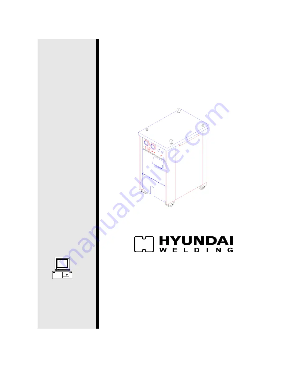
DYNAMIC AUTO
350M/500M
OPERATION MANUAL
HEAD OFFICE: ILSONG BLDG. 16th fl.157-37,
SAMSUNG-DONG, KANGNAM-KU, SEOUL, KOREA
TEL : (+82-2)6230-6062~5 FAX: (+82-2)522-2030
FACTORY : 9-2, SAEUM-DONG, ICHEON-SI, GYEONGGI-DO, KOREA
TEL : (+82-31)636-3100 FAX: (+82-31)636-3957
www.hyundaiwelding.com
Summary of Contents for Dynamic auto 350M
Page 11: ...VER 2 0 10 2 2 Manufacturer s Rating Label...
Page 24: ...VER 2 0 23 5 1 2 Crater ON 5 1 3 Crater HOLD...
Page 29: ...VER 2 0 28 SECTION 7 FUNCTION DIAGRAM 7 1 DYNAMIC AUTO 350M...
Page 38: ...VER 2 0 37 9 1 DYNAMIC AUTO 500M OPTION EX03 PCB CT1 INCLUDED...
Page 39: ...VER 2 0 38 SECTION 10 PARTS LIST 10 1 Main Assembly Dynamic Auto 350M...
Page 41: ...VER 2 0 40 10 2 Main Assembly EX PCB Type Dynamic Auto 500M...


