background image


10

Installation Steps


You will need a Philips screwdriver (cross head screwdriver), a Torx (T10) screwdriver and 

a spanner, to install the unit. 


  Caution: Be sure to observe proper electrostatic discharge precautions if any part 

must be removed from the unit.   

The installation steps are as follows: 


1.  Mount the unti in a rack, bracket or cabinet.   

2.  Connect accessories such as antenna cables and power cords to the unit. 


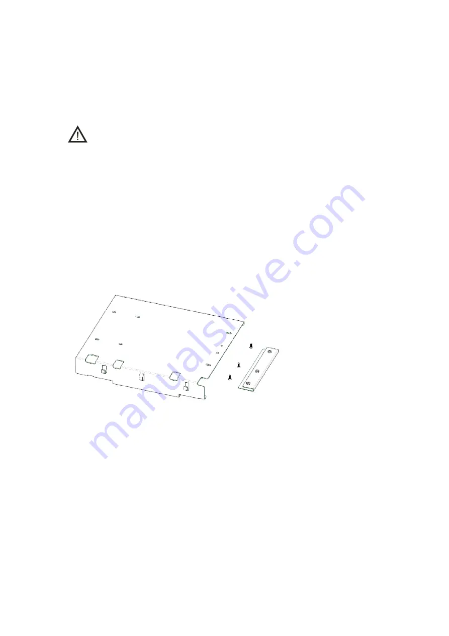
If a duplexer needs to be mounted 

If the unit needs to work with a duplexer , your will need to implement the following 

installation steps prior to the above steps 1 and 2.   

1.  Loosen the three screws on the bracket with a Philips screwdriver. 


2.  Install the optional duplexer and the bracket. Be sure to observe the specifications of 

the two antenna connectors on the duplexer, to determine which connector should be 

connect to the transmitter. Ensure the antenna connector connected to the 

transmitter is beside the rear panel of the unit. 


Take Hytera supplied duplexer as an example. If the transmitter is connected to the 

low cavity connector, the duplexer should be mounted with the front side facing 

upwards (see the following figure on the left); and if it is connected to the high cavity 

connector, the duplexer should be mounted with the front side facing downwards (see 

the following figure on the right). 


Summary of Contents for CHU-P0BA01

Page 1: ... CHU P0BA01 is endowed with ergonomic design reliable performance and comprehensive digital functions to deliver an advanced communication solution With CHU P0BA01 you canmake use of digital advantages to top the competition To ensure you get maximum benefit from the product please read this manual carefully before use ...

Page 2: ...rograms stored in memory or other media Laws in the PRC and or other countries or areas preserve for Hytera exclusive rights for Hytera computer programs The purchase of this product shall not be deemed to grant either directly or by implication any rights to the purchaser with respect to Hytera computer programs Any Hytera computer programs may not be copied modified distributed decompiled or rev...

Page 3: ...tion 6 Installation Overview 7 Before Installation 7 Installation Requirements 8 Installation Steps 10 Electrical Connections 13 Power Supply Connections 13 RF Antenna Connections 14 Post Installation Checklist 15 Status Indications 16 LED Indicator 16 Basic Operations 17 Turning the Unit On Off 17 Care and Cleaning 17 ...

Page 4: ...s in the Package Please unpack carefully and check that all items listed below are received If any item is missing or damaged please contact your dealer Duplexer Installation Kit Power Cord Channel Unit Owner s Manual ...

Page 5: ...Power Indicator 3 Unit Mode Indicator 4 Analog Mode Indicator 5 Slot 2 RX Indicator 6 Slot 2 TX Indicator 7 Digital Mode Indicator 8 Slot 1 TX Indicator 9 Slot 1 RX Indicator 10 Alarm Indicator 11 Programmable Keys 12 LCD Display 13 Channel Up Key 14 Menu Navigation Knob 15 Channel Down Key 16 Speaker ...

Page 6: ...el No Part Name No Part Name 1 TX Antenna Connector 2 Optional Connector 1 3 RX Duplex Antenna Connector 4 Optional Connector 2 5 Monitor Test Jack 6 Accessory Jack 7 DC Power Inlet 8 Ethernet Port 9 Ground Screw ...

Page 7: ... 2 Front Panel 3 RF PA Module 4 Excitor Module 5 RX Module Installation Proper installation can ensure optimum performance and reliability of the unit Be sure to read the following installation requirements and instructions carefully before you install the unit ...

Page 8: ... test of the equipment to verify proper installation Before Installation Before you install the unit at the site you are suggested to power on the unit and check it for proper operation 1 Applying Power Before applying power to the unit make sure the voltage of DC power supply or battery is compliant with the operating voltage range of the unit Then connect the DC power supply or battery to supply...

Page 9: ...ent operating in an area which is environmentally controlled and with the unit rack mounted the airborne particle level must not exceed 25μg m3 And for equipment operating in an area which is not environmentally controlled and with the unit cabinet mounted the airborne particle level must not exceed 90μg m3 Caution If the unit is to be installedin an area which is usually dusty dirty or does not m...

Page 10: ...manent damage to the unit The ground and lightning protection system is one of the most important considerations when designing a communication site Proper grounding techniques and lightning protection are closely related and the general category of site grounding may be divided into the following two sections Electrical Ground Ground wires carrying electrical current from circuitry or equipment a...

Page 11: ...to the above steps 1 and 2 1 Loosen the three screws on the bracket with a Philips screwdriver 2 Install the optional duplexer and the bracket Be sure to observe the specifications of the two antenna connectors on the duplexer to determine which connector should be connect to the transmitter Ensure the antenna connector connected to the transmitter is beside the rear panel of the unit Take Hytera ...

Page 12: ... 4 Loosen the 6 screws locking the PA heatsink remove all power data and RF cables from the PA and finally remove the PA heatsink 5 Mount the duplexer and fasten the 2 screws inside the housing and on the side panel respectively Then mount the PA heatsink and connect all the lines and cables ...

Page 13: ...xcitor module PA module Duplexer TX connector Duplexer antenna connector RX duplex antenna connector rear panel RX signal RX duplex antenna connector rear panel Duplexer antenna connector Duplexer RX connector RX module Diagrams of Assembled Unit Duplexer Mounted with Front Side Facing Upwards ...

Page 14: ...rical connections must be made This involves making the following connections DC power cord Antenna cables See the rear panel view for the positions of connectors Power Supply Connections 1 Ground Connection The unit is equipped with a ground screwlocated on the rear panel Connect ground wires to the screw 2 DC Power Supply or Battery Backup Connection ...

Page 15: ...e battery with an external charger Remove the battery from the unit when charging RF Antenna Connections TX and RX antennas are connected to two separate connectors shown in the rear panel view and there must be adequate isolation of 75 dB UHF or 85 dB VHF between them If only one antenna through a duplexer is connected at least 75 dB UHF or 85 dB VHF isolation between the TX and RX antenna ports ...

Page 16: ...e point they enter the building All aspects of the antenna design must comply with the relevant local regulations Post Installation Checklist After the unit has been mechanically installed and all electrical connections have been made power may now be applied and the unit should be checked for proper operation 1 Applying Power Before applying power to the unit makesure all boards are securely seat...

Page 17: ...unit transmitting on slot 1 digital Slot 1 TX Indicator flashes red Busy channel lockout transmission time out Slot 2 TX Indicator glows red Unit transmitting on slot 2 digital Slot 2 TX Indicator flashes red Busy channel lockout transmission time out Slot 1 RX Indicator glows green Unit receiving analog unit receiving on slot 1 digital Slot 1 RX Indicator flashes green Monitoring Slot 2 RX Indica...

Page 18: ... and heat dissipation to facilitate normal work Do not place irrelevant articles on top of the unit to ensure optimal heat dissipation Do not place the unit in corrosive agents solutions or water Unit Cleaning Clean up the dust and fine particles on the unit parts with a clean and dry lint free cloth or a brush regularly Use a non woven cloth with neutral cleanser to clean the keys control knobs L...

Page 19: ...standard must not be violated when using the product To ensure optimal performance and compliance with the occupational controlled environment RF energy exposure limits in the above standards and guidelines users should always adhere to the followings Gain of antenna must not exceed 7 1dBi Antenna Installation install the antenna at least 2 1 meters away from your body in accordance with the requi...

Page 20: ...d and operated with minimum distance 2 3m between the radiator and your body Cet équipement est conforme aux limites d exposition aux radiations IC CNR 102 établies pour un environnement contrôlé Cet équipement doit être installé et utilisé avec une distance minimale de 2 3m entre le radiateur et votre corps This device complies with Industry Canada license exempt RSS standard s Operation is subje...

Reviews: